The ancient Greek philosopher Heraclitus said that there is nothing permanent except change. Greek history aside, it’s easy to spot change in our current market because vehicle fuel delivery technology has evolved to include conventional, pulse-modulated, and direct fuel injection fuel delivery systems, with each having a specific set of components and testing issues. In the following text, I’ll explain how the basics of testing fuel delivery problems has changed and how some of the most common mistakes in diagnosing fuel delivery systems can be avoided.
CONVENTIONAL SYSTEMS
Conventional fuel delivery systems are commanded by the powertrain control module (PCM) to apply between 35 to 65 psi of fuel pressure to the fuel injectors. The PCM generally activates the fuel pump by grounding the primary circuit of the fuel pump relay. Fuel pressure on two-line systems is controlled by an external, vacuum-modulated fuel pressure regulator or, on a single-line system, by a non-modulated fuel pressure regulator mounted inside the fuel pump module assembly.
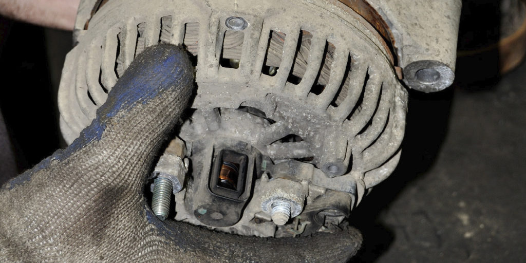
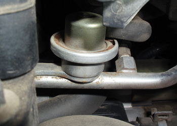
The two-line system returns excess fuel to the fuel tank via a separate fuel return line, while the single-line system releases excess fuel into the tank itself. Most conventional systems include a Schrader valve at the fuel injector rail to allow for mechanical pressure testing. See Photo 1.
When the ignition switch is turned on, the fuel pump is activated for several seconds to prime the fuel injectors. The fuel pump activates again during cranking, but deactivates when the ignition key is released. When the crankshaft position (CKP) sensor indicates to the PCM that the engine is running, the PCM continues to activate the fuel pump relay without input from the ignition switch.
PULSE-MODULATED SYSTEMS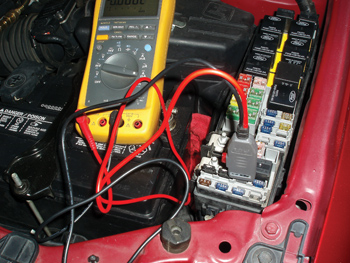
In contrast to conventional systems, pulse-modulated systems control fuel pressure by changing fuel pump speed. These systems are single-line systems that incorporate a fuel pressure sensor in the fuel injector rail. The PCM modulates the fuel pressure in relation to engine speed and load.
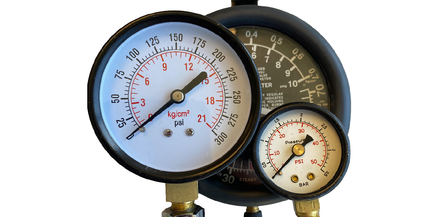
In most cases, an external fuel control module reacts to input by the PCM and modifies the pulse width or duty cycle of the current being delivered to the fuel pump. Pulse-modulated systems are generally diagnosed by using a scan tool to retrieve DTCs and to initiate diagnostics testing. See Photo 2.
DIRECT FUEL INJECTION
In response to EPA mandates for higher fuel economy and lower exhaust emissions, most auto manufacturers are now incorporating direct fuel injection into most current engine designs.
Direct gasoline fuel injection uses a conventional single-line, low-pressure fuel pump and integral pressure regulation system to supply fuel to a high-pressure mechanical fuel pump mounted on the engine. Some 2011 and newer vehicles might be equipped with a brushless fuel pump motor.
A fuel pressure sensor mounted in the fuel line monitors the supply pump pressure. A second pressure sensor mounted in the fuel injector rail monitors the high-pressure fuel injection pump. The high-pressure pump, which can develop as much as 3,000 psi on some models, is regulated by a pulse-modulated by-pass solenoid that adjusts fuel pressure according to engine demand.
Because high-pressure fuel can seriously injure a technician, direct fuel injection repairs require specific procedures that might include using a scan tool to relieve fuel pressure before disassembly. For safety reasons, many manufacturers require that all high-pressure fuel lines be replaced rather than re-installed. Special tooling is also required to install direct fuel injector seals.
Last, engine oil must meet OEM specifications to prevent premature wear on the engine camshaft and high-pressure fuel pump follower. Since the various direct gasoline injection-operating modes are too voluminous to address in this brief space, suffice to say that direct fuel injection requires scan tool-based diagnostics and a specific understanding of the system’s various operating modes and failure points.
CHECK THE BASICS FIRST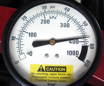
Symptom-based fuel pump diagnostics aren’t always accurate because a hard-starting complaint can be caused by something as simple as stale gasoline often found in private storage tanks and, more specifically, in above-ground storage tanks that expose the gasoline to extreme temperature changes. Because stale gasoline doesn’t vaporize properly, it causes hard starting and poor cold-engine performance. E-85 ethanol gasoline, which is intended for use only in flex-fuel vehicles, can also cause many different driveability complaints in non-flex fuel vehicles including a severe loss of power. 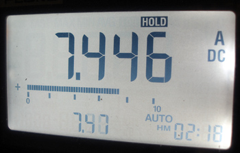
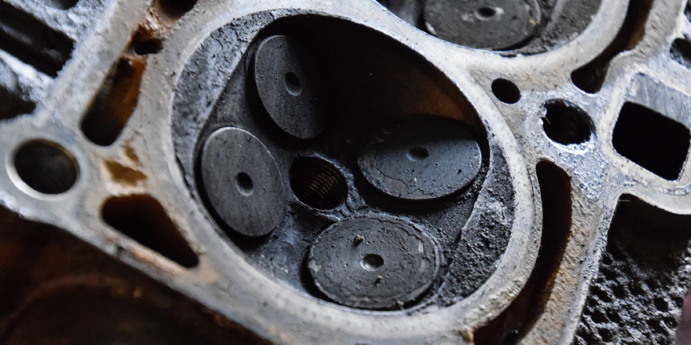
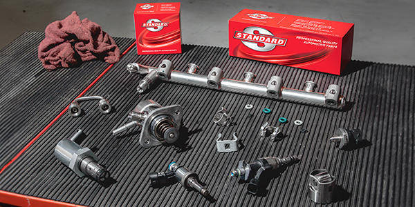
All too often, rusty gasoline can completely clog a recently installed fuel filter, so never assume that a filter isn’t clogged because it looks new. In addition, a defective mass air flow (MAF), barometric pressure (BARO), throttle position (TP), engine coolant (ECT) or intake air temperature (IAT) sensor can create driveability symptoms that mimic defective fuel pumps. Always compare the values displayed on the scan tool with real-time values. This is still another reason to use your scan tool to evaluate sensor data streams and search for pending trouble codes before condemning the fuel pump. See Photos 3 and 4.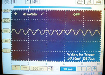
In some cases, the fuel level sensor can be stuck or indicate a false reading. In any case, always add a few gallons of gasoline during testing to ensure that the fuel pump is immersed in fuel. In addition, visually inspect the fuel tank for dents or other damage that might interfere with pump operation. See Photo 5.
CRANKING, NO-START TESTING
I recommend connecting a scan tool as the first step in diagnosing a suspected fuel pump failure. First, the scan tool can help identify the type of fuel delivery system used on the vehicle. A pulse-modulated system will, for example, show a pulse-width parameter and perhaps a fuel pressure parameter in the scan tool data. The direct fuel injection system should display, among many other parameters, low- and high-pressure fuel pump data.
The second step is to poll the various modules for related trouble codes and to access available bi-directional fuel pump controls. Some PCMs might not, for example, activate the fuel pump if the ignition key is missing its identification chip or if the vehicle security system has detected tampering. A trouble code will generally be stored if the vehicle security system can’t identify the key. In other cases, the PCM software might have enough sophistication to store a pending trouble code for a fuel delivery failure. In these instances, retrieving a related trouble code will save many wasted steps.
In addition, many scan tools include bi-directional controls that allow the technician to test the fuel pump relay and pump circuit by electronically activating the fuel pump. Here again, a simple activation test saves many pinpoint electrical tests. If the fuel pump activates, complete the testing by adding a gallon of fuel to verify fuel level sensor operation and attach a mechanical gauge to measure fuel pressure on conventional systems.
If the fuel pump doesn’t activate by scan tool command on a conventional system, remember that some manufacturers install an inertia switch in series with the fuel pump to deactivate the pump during a collision. This switch is commonly tripped during off-road driving or minor impacts. Other systems might use networked electronics to deactivate the fuel pump if the air bags are deployed.
Some PCMs might also use data from the airflow or CKP sensors to deactivate the fuel pump if the engine has stalled. Consequently, a bad sensor or connection might inhibit fuel pump operation. Other systems might use an oil pressure switch to deactivate the fuel pump if a stalling or lack of lubrication condition occurs.
As a last step, check for available voltage and for a clean ground at the fuel pump tank connection. On older conventional systems, the ground might be located on the vehicle frame. On later systems, manufacturers moved the fuel pump ground inside the passenger compartment where it’s less susceptible to corrosion.
Fuel-related loss of power complaints can generally be addressed by recording short- and long-term fuel trim numbers with a scan tool while road-testing the vehicle. If the short-term fuel trims begin to exceed about 20% at wide-open throttle (WOT) and, perhaps, stores a P0171 on in-line engines and a P0174 on V-type engines, the engine has a fuel delivery problem.
But, remember, that a faulty MAF sensor can commonly cause high positive fuel trims. Remember also that calculated engine loads are generally at least 80% at WOT. If the calculated engine load is less than 80%, suspect a dirty or defective MAF or, perhaps, a defective barometric pressure sensor. If calculated load exceeds 80%, suspect a fuel delivery problem in the fuel pump, filter or fuel lines.
SIDEBAR
The Importance of Scope Testing
Fuel pressure and volume tests are not always conclusive regarding the condition of the fuel pump. Some fuel pumps will pass these tests and yet cause an intermittent starting problem. This condition is typically the result of a worn commutator bar on the armature.
Using a lab scope is the best way to evaluate the condition of a fuel pump. Even slight inconsistencies will show up in a waveform that took milliseconds to record. By analyzing a fuel pump waveform, you can quickly identify problems that would otherwise go undetected using conventional pressure and volume tests. A good fuel pump waveform consists of a series of small uniform humps. Examining the current waveform of each commutator bar during a complete rotation of the fuel pump will give an accurate indication of the internal condition of the fuel pump. Any spikes indicate problems with the brushes and/or commutator segments.
The scope also displays the average current. It’s normal for a fuel pump current to be higher when the pump is first energized and begins to push fuel, though the amperage should quickly drop and stabilize. Low current readings are indicative of electrical problems, such as brush and commutator wear, a poor ground or high-resistance connections. Excessive fuel pump current indicates that the pump is being overloaded. This may be the result of a restricted fuel filter, a clogged strainer or blocked return line. Check the appropriate service manual for fuel pump current specifications.
Courtesy of Delphi Product & Service Solutions