On June 15, 1911, Charles F. Kettering was awarded a patent for an electric self-starter for automobile engines. Thinking out of the box, Kettering designed a small, high-torque motor that would deliver a burst of energy lasting only long enough to initiate the internal combustion cycle. Fortunately for modern commuters, Kettering’s electric self-starter transformed the automobile from a temperamental novelty item into a practical means of transportation.
COMPONENT BASICS
From a historical view, it’s important to remember that Kettering’s conventional field-coil starter required battery power to create the magnetic field needed to make the starter armature turn. During the 1980s, field-coil starters were phased out in favor of “ferrite” permanent-magnet starters.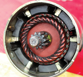
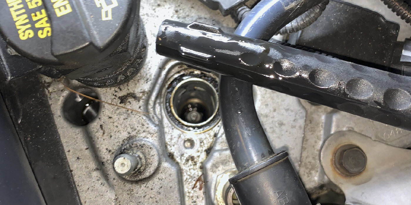
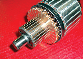
Since the fields in permanent magnet starters don’t require battery power, permanent-magnet starters require much less current to crank an engine. The result is a much lighter, far more efficient starter motor. But, because permanent or “ferrite” magnets are made of a brittle ceramic material, they are vulnerable to cracking caused by sudden impacts. Cracked magnets can be tough to diagnose, which is why it’s usually better to replace the starter as an assembly than to repair or rebuild it. See Photo 1.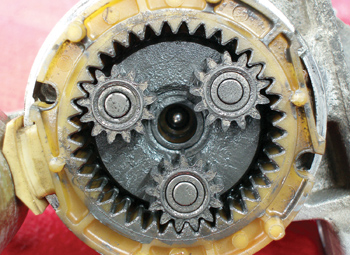
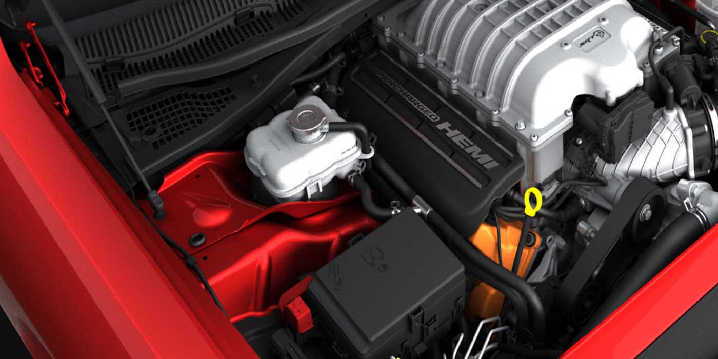
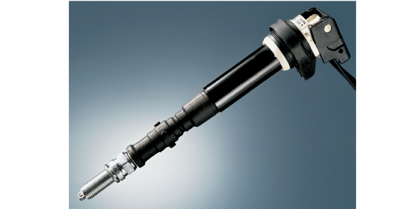
In addition, the rotating mass of the starter armature is reduced to create a more compact starter motor assembly. 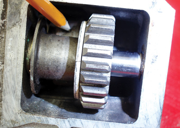 As pictured above (see Photo 2), the armature on most modern starters terminates into a sun gear mating with a set of planetary gears (see Photo 3) provide the initial gear reduction for the starter. A secondary reduction gear can also be used on starters like the one used to illustrate this story. See Photo 4.
The starter “solenoid” is actually a combination of an electric relay and solenoid. The relay portion electrically connects the starter armature to the battery. The solenoid portion mechanically engages the starter’s drive pinion with the engine’s flywheel gear. While modern solenoids usually incorporate two high-amperage terminals and one low-amperage, primary activation terminal, some older designs might incorporate an additional primary “by-pass” terminal that was originally designed to boost ignition coil voltage during cranking. In some applications, the by-pass terminal is unused and remains a vestigial remnant of past technology.
The starter over-run or one-way clutch is a simple roller-type clutch that’s designed to release when the engine speed exceeds cranking speed. In rare instances, the clutch will seize, which can cause the starter armature to explode from centrifugal force as the engine accelerates. In other cases, the clutch will simply wear out, which usually results in a “whirring” sound, indicating that the starter motor is running, but not engaged to the flywheel.
STARTER ACTUATION SYSTEMS
For safety’s sake, the starter’s primary circuit is routed through a neutral safety switch on automatic transmission vehicles and through a clutch safety switch on manual transmission models. With that said, current practice is to reduce the electrical load on the ignition, neutral safety and clutch switches by inserting a starter relay into the starter primary circuit. In this case, the above switches activate the starter relay switch rather than the starter’s primary solenoid circuit.
Keep in mind also that modern technology in some vehicles has delegated the starter engagement process to the Powertrain Control Module (PCM). In this system, turning the ignition switch or pressing the “start” button simply commands the PCM to engage the starter motor. Failures in these systems should first be diagnosed with a scan tool and by using diagnostic techniques similar to those used in any other system controlled by the PCM.
BATTERY DIAGNOSTICS
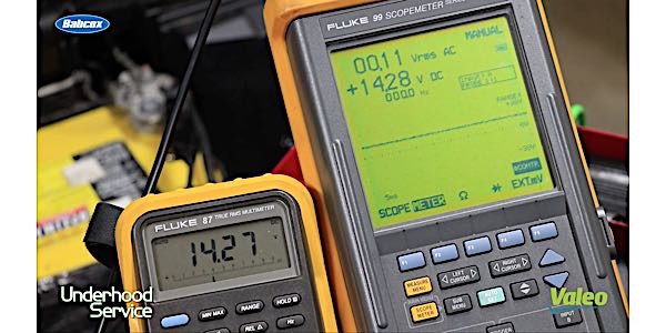
The first step is to make sure that the battery terminals and cables are free of corrosion. Next, determine the battery state of charge (SOC) and condition by testing with a conductance or variable-load, carbon pile battery tester. Recharge or replace the battery as required. Voltage drop from the battery to the starter can be measured by attaching a voltmeter in parallel to the positive battery terminal and to the solenoid B+ terminal.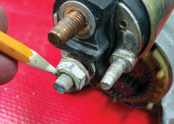
The rule of thumb is that voltage drop shouldn’t exceed 0.5 volts during cranking. The voltage drop on the negative ground terminal can similarly be measured by attaching the voltmeter lead to a clean area on the engine block and to the battery B- terminal. Here again, the voltage drop shouldn’t exceed 0.5 volts. See Photo 5.
STARTER CURRENT DIAGNOSIS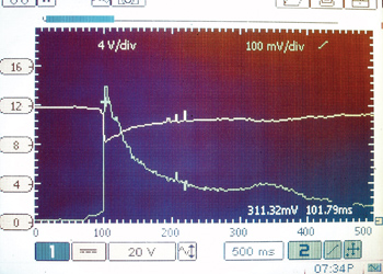
Most starter-related electrical failures can be diagnosed by measuring current flow into the starter. Actual current flow to the starter can be measured by attaching a 600-amp inductive current probe to the battery positive or negative cables. The probe can be attached to a multimeter with a minimum/maximum (min/max) recording feature or to a two-channel lab scope. To illustrate how a starter works on a vehicle in good condition, I’ve included a lab scope recording of battery terminal voltage and starter amperage draw. See Figure 1.
The amperage draw begins from the “zero” point at the left. The initial amperage drawn by the solenoid primary circuit occurs at 70 milliseconds (ms). If the voltage remains at zero, it’s likely that the system has a bad neutral or clutch safety switch, or that the starter relay is defective. If the solenoid amperage remains at 2-3 amps, the solenoid doesn’t have continuity to the starter. Bad solenoid contacts, worn starter brushes or an open-circuit armature can be the cause. In this case, the primary symptom will be a clicking noise as the solenoid primary circuit activates. Any of the above failures can result in an intermittent starter engagement complaint.
Once the solenoid closes the circuit at 100 ms, the amperage draw increases to 311 amperes at the trigger point. As the engine cranks, the amperage draw declines until approximately 300 ms. At about 300 ms, amperage rises slightly as the torque load on the starter is momentarily increased due to a possible variation in fuel delivery or spark advance.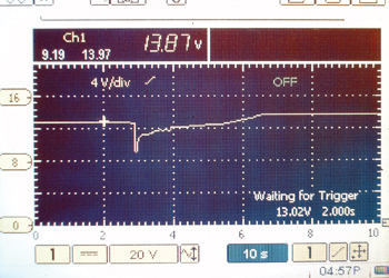
Similarly, battery terminal voltage spikes down to nearly 8.0 volts at 100 ms as cranking amperage is suddenly drawn from the battery. The battery terminal voltage begins to rise to about 10.0 volts at 200 ms as the starter amperage begins to stabilize. As the engine begins to crank, 10.0 volts should be considered the minimum voltage. If the battery won’t maintain 10.0 volts during cranking, the PCM might fail to process data or activate the injector and ignition system drivers. See Figure 2.
BATTERY VOLTAGE GRAPHING
Graphing available battery terminal voltage also provides a direct insight into battery condition. Charging voltage should be achieved approximately two seconds after the engine starts. If charging voltage doesn’t increase within that time interval, it’s likely that the battery doesn’t have enough remaining plate capacity to fully support starter current draw. In any case, using a lab scope to display available battery voltage and amperage discharge is an easy way to quickly evaluate battery, starter and starter activation systems.
A LOOK AT IDLE/STOP TECHNOLOGY
We’re beginning to see “idle/stop” or “stop/start” technology enter the non-hybrid import market, with fuel savings ranging from an estimated 5 to 15% in normal driving. Although a version of idle/stop technology was popularly introduced in a European version of Volkswagen in 1983, the technology has a number of issues, including how to power the HVAC and lighting systems while the engine is stopped.
Because idle/stop technology obviously requires a rapid discharge/recharge cycle, the absorbed glass mat (AGM) battery most closely meets those requirements. Similarly, idle/stop engine cranking systems include integrated starter/generator systems mounted at the flywheel or connected to the front of the crankshaft by the drive belt. Others use an “enhanced” starter motor system that is built to withstand repeated cranking cycles. With the advent of direct fuel injection and electronic valvetrains, some manufacturers have explored using fuel and spark timing alone to initiate the internal combustion process.