If you’re like me, you more often than not find a correct diagnostic direction by going back to what trainers are fond of calling “The Basics.” I capitalized “The Basics” because they are the foundation upon which all of us should be building our diagnostic strategies. The Basics were brought to mind recently when I visited a neighboring technician who mentioned in passing that he’d “really dug himself into a hole” on an oxygen sensor diagnosis. A quick look revealed that the problem was in “how” he interpreted his scan tool data, but more about that later.
OXYGEN SENSOR TYPES
Before we get too far into basic oxygen sensor diagnostics, it’s important to note that four types of oxygen sensors are in current use: the heated and unheated zirconia and titania sensors, and the modern heated zirconia-based planar and wideband sensors. For the purpose of this story, we’ll concentrate on zirconia and planar sensors.
The unheated and heated zirconia thimble types are self explanatory, with the unheated types relying on hot exhaust gas to heat them to operating temperature, and the latter containing an electric heater that quickly heats the sensor to its required 625° F operating temperature. When the zirconia sensor reaches operating temperature, it begins generating a zero-to one-volt input to the PCM. Planar sensors are zirconia sensors that have been reconfigured to significantly reduce the mass of the sensing element and to incorporate the heater into the element. This design also reduces the current needed to bring the sensor to operating temperature.
ZIRCONIA BASICS
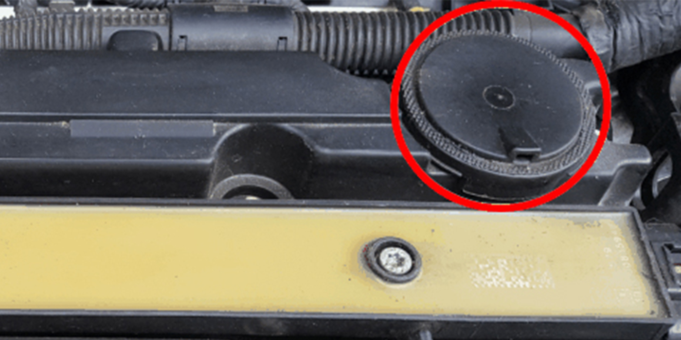
In brief, zirconia sensors consist of a zirconia thimble coated on both sides with a thin layer of platinum. The zirconia thimble generates a very low voltage when significant differences in oxygen (O2) content occur between the atmospheric and exhaust oxygen sides of the thimble. When a low percentage of O2 is detected in the exhaust stream, the zirconia sensor sends a 0.9 voltage signal to the PCM. When a high percentage of O2 is detected in the exhaust stream, the voltage signal falls close to zero. Because one side of the zirconia thimble must be exposed to atmospheric oxygen, it’s important for the sensor to “breathe” through the sensor’s cover and, on some designs, through the sensor wire. For this reason, zirconia sensors fail when a coating of viscous fluid like engine oil prevents atmospheric oxygen from reaching the sensor thimble.
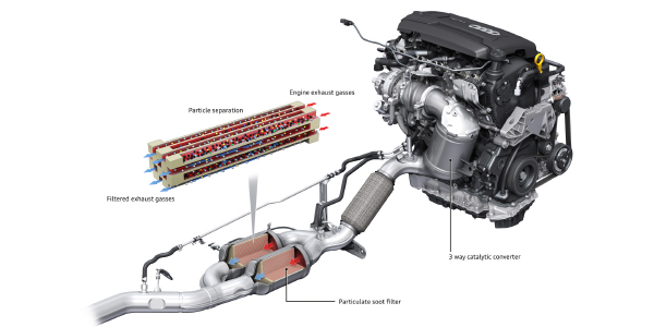
An emissions-controlled engine operates best at a chemically correct or “stoichiometric” air/fuel ratio (a/f) of 14.7 units of air to 1 unit of gasoline (14.7:1). When the O2 sensor detects stoichiometric, it sends a 0.450-volt signal to the PCM. For a variety of reasons, it’s difficult for most PCMs to maintain perfect fuel control, so the fuel system is designed to “switch” from rich to lean, which produces an O2 sensor voltage from about 0.2 volts to 0.8 volts. When viewed on a lab scope, this voltage switch appears as a waveform with 0.450 volts being the centerline value. The only exceptions to the above statement are the downstream oxygen sensors on OBD II vehicles, which are designed to monitor catalytic converter performance by relaying a non-switching voltage signal to the PCM.
 FAILURE POINTS OF ZIRCONIA SENSORS
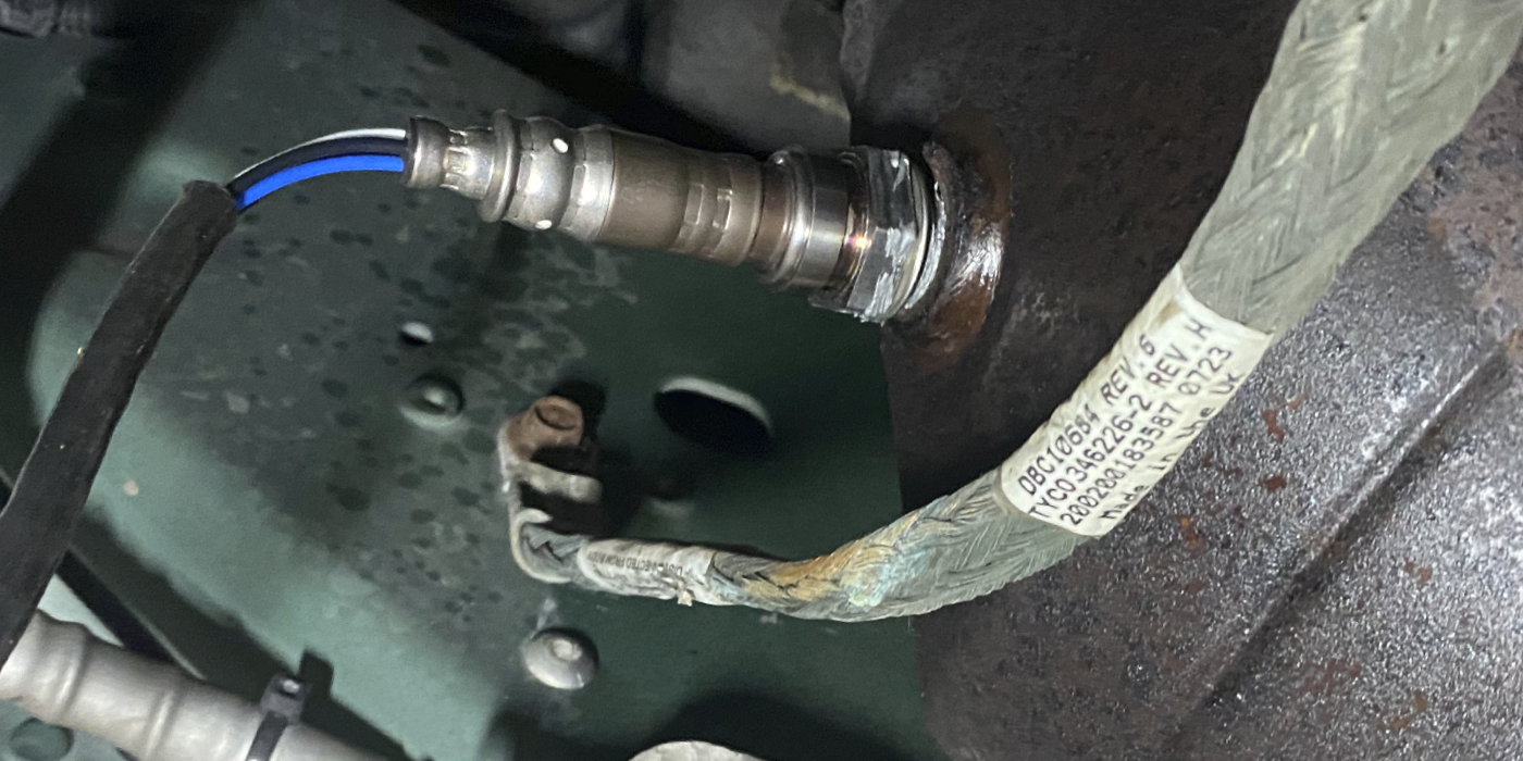
Early zirconia sensors failed regularly due to ethyl lead and silica contamination in service station storage tanks, and from oil ash and coolant contamination in the exhaust gas stream. Today’s zirconia sensors fail most often because carbon, oil or coolant ash accumulates on the thimble or because the heater circuit fails inside the sensor (See Photo 1).
Thimble contamination usually results in the switching rate or cross-count time from 0.2 to 0.8 volts becoming slower. A good thimble shield should wipe off to bare metal. If the thimble shield feels rough to the touch, it’s probably contaminated.
Last, a zirconia sensor can develop a “voltage bias,” which means that the sensor’s centerline voltage has changed. Instead of swinging from 0.2 to 0.8 volts, it might swing from, let say, 0.3 to 0.9 volts, which is called a “rich bias.” A lean bias would be a voltage swing starting at less than 0.2 volts and peaking at less than 0.8 volts. If the voltage exceeds 1.0 volts, the problem might be caused by a bad oxygen sensor ground or by battery voltage leaking into the O2 sensor input to the PCM. In some cases, the PCM limits B+ voltage, so although the datastream display indicates less, B+ voltage is indeed present in the circuit.
 BENCH TESTING ZIRCONIA SENSORS
The voltage swing of a zirconia sensor can be measured with a 10 megohm impedance digital multimeter (DMM). A meter without the 10-meg impedance will essentially short the O2 sensor circuit and provide an inaccurate voltage reading. The sensor output can also be tested with a lab scope, which displays the voltage range and time base as well (See Photo 2).
A zirconia sensor can be bench-tested by heating the thimble with a propane torch to at least 625° F. In this case, the thimble shield should glow a dull cherry red and produce a 0 to 0.9-volt swing as the torch flame is passed across the thimble. Carbon contamination caused by a rich air/fuel ratio can often be removed by heating the thimble shield with a propane torch (See Photo 3).
 IN-VEHICLE ZIRCONIA SENSOR DIAGNOSIS
Because of greatly increased computing capacity, OBD II systems provide far more comprehensive methods of evaluating oxygen sensor performance and, in most cases, are far more conclusive than trying to probe the sensor with a scope or meter.
UNDERSTANDING CODES AND DATA
On many applications, the engine must reach full operating temperature before the oxygen sensor monitor runs and the PCM will store an oxygen sensor trouble code. Because modern PCMs rely on O2 sensor input to go into closed-loop fuel control, a heater circuit failure quickly enters a diagnostic trouble code into the diagnostic memory on OBD II vehicles. Keep in mind that conventional O2 heater systems are protected by fusible links that may burn due to a short-to-ground in the heater circuit. In more current systems, the heater circuit might be pulse-width modulated by the PCM.
 As for thimble performance, the PCM measures many different performance parameters to determine if the thimble voltage output has become “lazy,” “biased,” or “nonexistent.” Because these specifications are written into the PCM’s operating software and might be modified by a future PCM recalibration, the specific parameters aren’t as important as being able to diagnose the trouble codes that they may generate.
In some software configurations, a severe vacuum leak can lead the PCM to believe that it has a zirconia sensor failure simply because, due to an excess of air in the exhaust stream, it no longer “sees” a voltage output from the sensor. Consequently, it’s important to test oxygen sensor response by adding propane to intake air or by removing a major vacuum hose to add air to the exhaust stream flow.
Going back to the technician in our opening paragraph, the fact that he had retrieved oxygen sensor-related trouble codes did not mean that the oxygen sensor itself had failed. In this case, the data stream indicated that, while three of the four sensors performed normally, the allegedly “bad” downstream sensor was producing a constant reading of 0.451 volts. Keep in mind that, while the downstream sensors don’t switch voltage, they normally produce more than 0.451 volts and, if two downstream sensors are used, they should produce similar voltages.
In this particular application, the PCM was substituting a very recognizable default value or bias voltage of 0.451 volts into the O2 sensor circuit. That particular voltage value indicated that the sensor circuit had an open-circuit condition. A subsequent inspection revealed a broken wire in the oxygen sensor circuit. As with most oxygen sensor diagnostics, this wasn’t a case of employing expensive diagnostic technology to find the fault, but rather the simple matter of just understanding and applying “The Basics” to find a relatively rare, but simple oxygen sensor circuit failure.