Although the basic ignition switch has remained unchanged for many years, the way it supplies electrical current to modern on-board electronics has made it a key factor when diagnosing intermittent failures in various electronic operating systems. Going back into automotive history, the ignition switch’s sole purpose on early imports was to energize the primary ignition system circuit as the engine was being cranked. In many cases, a lock cylinder and key were added to discourage auto theft and, in other cases, a steering shaft lock was incorporated into the ignition switch to further inhibit theft.
The ignition switch’s job became more complex as accessories like radios, electric windshield wipers and heater blower motors were added to vehicles. Moving beyond its original role as a simple on-off switch for the engine’s ignition system, the ignition switch was also designed to supply electricity through an accessory position on the switch. This allowed accessories to function in a key-on, engine-off situation without overheating and oxidizing the contact points in the engine’s distributor. As more accessories like power windows, power door locks, power seats, air conditioning and electronic automatic transmissions were added, the ignition switch’s job became even more demanding.
Today, the ignition switch is a complex device that powers numerous electrical and electronic systems throughout the vehicle. In fact, the newest version of the conventional ignition key is an electronic device that identifies the driver and allows him to activate the starting system on demand. But that’s another story, so let’s stick with exploring the basics of the conventional ignition switch and its operation and diagnosis.
IGNITION SWITCH CONFIGURATIONS
Most early ignition switches transmitted all of the electrical current needed to supply the vehicle’s ignition system and accessories. As accessories were added, the amperage load through the ignition switch became too high for most switch configurations. To reduce amperage loads through the ignition switch, import manufacturers began adding electrical relays to the ignition switch circuit. In this configuration, the ignition switch supplies very small amperages to activate a relay that, in turn, activates high-amperage devices like HVAC blower motors, electric cooling fans and similar devices.
For lower-amperage accessories, the ignition switch transmits amperage to a fuse box that is designed to protect the ignition switch and its companion wiring from catastrophic overheating if a component circuit is shorted to ground.
FAILURE PATTERNS
Most ignition switches incorporate spring-loaded, sliding contacts to transmit adequate amperage to individual fuse and relay circuits. As these contacts begin to wear, they may lose their ability to make perfect mechanical contact. In other instances, they may begin to oxidize due to heavy amperage flow. In either case, the contacts begin to develop electrical resistance that reduces amperage flow through the ignition switch.
Very few ignition switches fail catastrophically. Most begin to fail intermittently and are usually sensitive to temperature and humidity. If the internal sliding contacts are heavily greased during assembly, the grease may begin to harden and inhibit mechanical contact during cold weather. If the switch fails during heavy accessory loads, the internal sliding contacts may have become heavily oxidized or succumbed to heat distortion and loss of mechanical integrity. In any case, most ignition switches give ample warning of an impending failure via intermittent ignition or accessory operation under various conditions of temperature and electrical load.
DIAGNOSTIC STRATEGIES
Although each nameplate has a proprietary design for its ignition switch and electrical system, diagnosing any modern ignition switch problem requires some common tools of the trade, which follow in the next several paragraphs.
Late-model imports have extremely complex electrical component arrangements connected by even more complex wiring systems. Most wiring schematics simply illustrate the electrical relationship between the various components and the color-coding on the wires that connect the components. Unfortunately, while a wiring schematic is indispensable to any electrical system diagnosis, it usually won’t illustrate the complex routing of the various fuse and relay circuits powered by the ignition switch.
Power distribution charts are perhaps the most accurate illustration of how the ignition switch distributes electricity through the fuse box and to the various electrical relays. In addition, power distribution charts also list the individual accessories that are powered by the various fuses or relays.
Of course, we must remember that a ground connection completes each electrical circuit supplied by the ignition switch. The ground distribution chart not only identifies the ground for each fuse, relay and component, but it also identifies where the ground is located on the vehicle chassis.
Although bus and splice charts are entirely different, I’ll lump them together for the sake of editorial simplicity. Simply, a bus communications chart identifies the wires by which the various on-board computers and modules communicate with each other. In most cases, bus wires can be identified as pairs of wires twisted together which typically carry pulsed, low-voltage signals of about 2.5 volts. In any case, it’s important to not confuse a bus communications wire with a wire that transmits battery voltage.
As for splice charts, it’s important to be able to verify the location and integrity of various splices in the electrical wiring. In some cases, reduced voltage in an electrical circuit may be the fault of a bad splice rather than a bad contact in the ignition switch.
VOLT, OHM & AMP METERS
Because it’s necessary to measure very subtle differences in voltage, resistance and amperage throughout an electrical system, it’s extremely important to use professional-grade, 10 meg-ohm impedance meters. Meters that don’t meet this standard will often provide inaccurate and misleading readings, which will cause a technician to make major errors in ignition switch diagnostics.
DIAGNOSTIC SCENARIOS
Worn ignition switches may be indicated by improbable occurrences such as the Malfunction Indicator Light (MIL) being illuminated and multiple diagnostic trouble codes (DTCs) being retrieved from a powertrain control module’s (PCM’s) diagnostic memory. Instead of the multiple DTCs being caused by multiple component failure, the problem may be caused by the ignition switch not supplying adequate amperage to the operating system itself.
A good illustration might be six or more DTCs contained within a specific system like an electronic automatic transmission or four-wheel-drive transfer case. It’s highly improbable, for example, that six shift solenoids contained in an automatic transmission would fail simultaneously. The most likely place to start a diagnosis would be at the ignition switch terminal supplying voltage and amperage to the transmission solenoid circuit.
VOLTAGE VARIATIONS
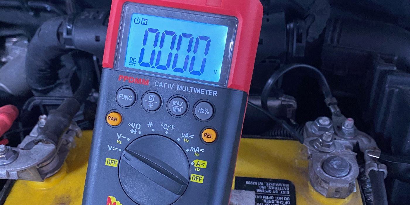
Continuing this scenario, the worst procedure is to disturb electrical connections, wiring or components in the system. Instead, the safest procedure is to measure the voltage available at the fuse that supplies the transmission solenoid circuits. By connecting our voltmeter to a good ground and measuring the available voltage at the fuse, we can determine if high resistance in the ignition switch is reducing amperage flow to the fuse and the components which it powers.
If a battery voltage of 13.5 volts is available at other fuses and only 9.5 volts is available at the transmission solenoid fuse, we might conclude that resistance has developed in the ignition switch and is starving each of the transmission solenoids of electrical amperage. Since the PCM can detect a solenoid or solenoid circuit failure by measuring the amperage flow through the ground connection in the PCM, the PCM may store a DTC for each of the affected solenoids.
Although this is only one diagnostic scenario, the procedure is similar for diagnosing many other electrical systems supplied by the ignition switch. It’s important to remember any diagnostic scenario is dictated by the vehicle’s component configuration as illustrated in a wiring schematic or power distribution chart. The remainder relies primarily on the individual technician’s experience, knowledge and diagnostic ingenuity.