 For veteran technicians, it’s no wonder that the internal combustion engine (ICE) has been pronounced “dead” on more than one occasion. After having gone through the gas turbine craze during the early 1960s and the rotary engine fad of the 1970s, it comes as no surprise that we’re witnessing still another resurrection of the reciprocating internal combustion engine in the form of gasoline direct fuel injection.
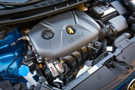
Fast-forwarding past throttle body and multiport fuel injection, we’re now looking at gasoline direct injection (GDI) systems, combined with ancillary developments like turbocharging, variable valve timing (VVT), variable cylinder displacement and advanced combustion chamber design, as the working model for current gasoline engine technology.
WHY GDI WORKS
Most of us are familiar with fuel and spark mapping in conventional engines in which spark advance and air/fuel (a/f) ratios are continuously modified to meet different engine load and speed conditions. The difference between GDI and conventional fuel injection systems is that GDI systems can use different operating modes to inject gasoline directly into the engine’s cylinders. Although the terminology among manufacturers might differ, the various modes can include power, homogenous, stratified, homogenous stratified and homogenous lean among others.
To better understand, let me describe several of the above modes. Since most GDI systems use at least a 10:1 compression ratio, the power mode is slightly richer than normal to cool the combustion chamber and dampen any tendency to detonate. The homogenous mode, as the name implies, indicates that the a/f mixture is evenly distributed throughout the combustion chamber at a 14.7:1 ratio.
In contrast, the homogenous stratified charge consists of a lean a/f mixture being injected into the cylinder, followed by a rich a/f mixture located at the spark plug. The rich a/f mixture is easily ignited by the spark plug and follows its function of igniting the lean a/f mixture. Due to the boundary layer of air along the surfaces of the combustion chamber, the lean a/f mixture tends to burn more completely than in port-injected engines. Keep in mind that not only can various “layers” of the a/f mixture be controlled, the timing and duration, and even the number of injection periods per combustion cycle, can be controlled by the PCM.
GDI CONFIGURATIONS
Because gasoline direct injection was popularly introduced during the 1990s, the configuration of any GDI system will vary according to age and application. Nevertheless, as an overview, the heart of the GDI system is a low-resistance conventional magnetic solenoid injector or a piezoelectric fuel injector, a high-pressure mechanical fuel pump, a contoured combustion chamber and a modern air/fuel ratio sensor.
 In contrast to the magnetic solenoid injector, the piezoelectric injector is composed of crystal wafers. When the wafers are electrically energized, they expand to produce the high mechanical pressures needed to open the injector pintle valve under 2,000 psi of fuel pressure. These crystal wafers are stacked in the GDI fuel injector so that they can nearly instantaneously pull the injector pintle valve open to admit fuel to the cylinder. Due to their design, operating voltages can range up to 90 volts at 15 amperes of current flow. Nozzles vary in design to ensure that the stream of fuel entering the cylinder conforms with the shape of the combustion chamber.
The high-pressure mechanical fuel pump, which is driven by one of the engine’s camshafts, is supplied by a conventional, single-line, in-tank pump. Fuel pressure on the mechanical pump is usually controlled by a pulse-modulated bypass solenoid mounted on the pump body.
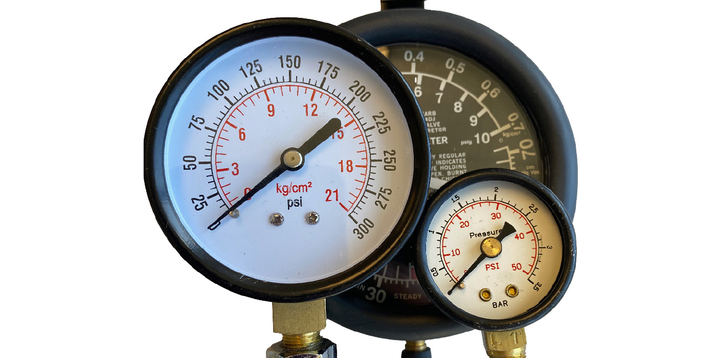
Since direct fuel injection requires high fuel pressures to overcome combustion pressures created in the engine’s cylinders, a typical high-pressure fuel pump can produce in the neighborhood of 2,000 psi maximum fuel pressure, depending upon operating conditions. Fuel pressures are monitored by a high-pressure sensor located in the fuel rail and a low-pressure sensor located in the fuel supply line.
Modified combustion chamber design is another major feature of GDI systems. Keep in mind that the injector can be positioned in the center or to the side of the combustion chamber or against the cylinder wall. Center-mounted injectors can use a cup-like recess in the piston to shape and contain the incoming fuel charge.
Similarly, side-mounted injectors can use channels and recesses in the piston head to help shape the incoming fuel charge. And, since the stratified or “lean-burn” modes can drastically increase piston temperatures, many GDI engines have oil nozzles mounted in the crankcase, underneath the pistons, to cool the piston domes.
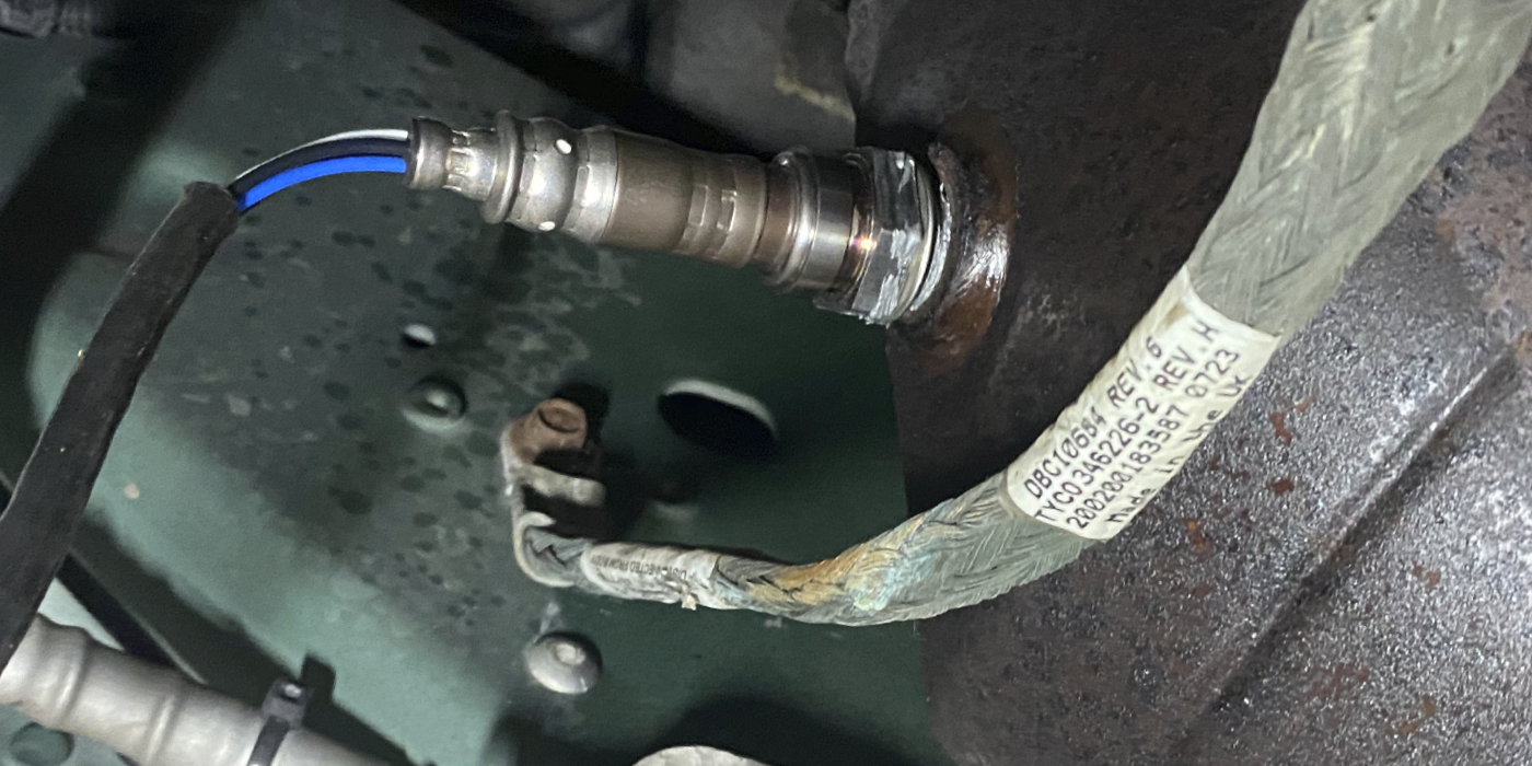
Some systems also use a tumbler flap mounted in the intake port to help direct the air charge into the cylinder in various modes. More unique to GDI systems, the cooling effects of injecting fuel directly into the engine’s cylinders allows engineers to use 10:1 to 13:1 compression ratios. Last, because a/f ratios can become very lean, the now-familiar wide-band a/f ratio sensor must be used to monitor exhaust stream gases.
ADVANCED OPERATING STRATEGIES
By itself, GDI is a refinement that provides better fuel control and combustion efficiency. But when combined with variable cylinder displacement, variable valve timing and turbocharging, GDI might be revolutionizing current engine technology. The most important point in modern engine technology is that engineers are now increasing combustion efficiency by using variable displacement engines to reduce pumping losses. They accomplish this by reducing the intake manifold vacuum and simultaneously increasing cylinder running compression at idle and low-throttle openings.
To illustrate, disabling three cylinders on a typical V6 engine requires an increase in throttle angle to supply air at a lower intake manifold vacuum to the remaining three cylinders. Since there is less torque because the engine is no longer running as a vacuum pump, the engine produces more power. In addition, the running compression pressure on the remaining cylinders is now increased at idle and, therefore, tends to burn the a/f mixture more efficiently in the operational cylinders.
As you might suspect, a high-compression GDI engine running at relatively high combustion temperatures and higher compression ratios tends to produce higher levels of nitrogen oxides (NOX). Some GDI engines, like Mazda’s SKYACTIV engine, use VVT to help reduce NOX production by changing the valve timing to more effectively manage the engine’s running compression. In some applications, changing the exhaust camshaft timing during the valve overlap cycle can produce an EGR effect by allowing a small volume of exhaust gas to enter the cylinder on the intake stroke.
 Lastly, improvements in turbocharging systems, such as variable vane technology, have reduced the “turbo lag” that characterized earlier systems. Turbocharging has also allowed engineers to reduce rotating friction by reducing engine displacements. So the current trend, or “revolution,” in engine design has combined GDI with ancillary developments like turbocharging, VVT, variable cylinder displacement, advanced combustion chamber design and modern a/f ratio sensors to produce small displacement, world-class engines that can be used in a variety of vehicle platforms.
SAFETY ISSUES
High-pressure direct injection poses some unique safety issues. Because any liquid pressurized to 2,000 psi can literally cut like a knife, a technician should be mindful that recommended safety procedures must be used to bleed off the extremely high fuel pressures present in the injector rail. Some manufacturers recommend disabling the fuel pump with the bi-directional controls included with most scan tools, then starting and running the engine until it stalls. Other manufacturers prefer alternate methods, so it pays to research applicable service information before attempting to diagnose or repair any GDI system.
Due to safety issues, manufacturers require that all O-rings and most high-pressure steel fuel lines be replaced with original equipment (OE) if removed for injector replacement or any related service repair.
OPERATING ISSUES
The problem of carbon accumulating on the intake valve seat is unique to direct fuel injection because the injected gasoline no longer washes carbon deposits from the intake valve seats. Most of the carbon deposited on the intake valve seats originates from the exhaust gas recirculation (EGR) and positive crankcase ventilation (PCV) gases passing through the intake valve into the combustion chamber. (See the article “Direct Injection Issues & Carbon Deposits,” in the September 2013 issue of ImportCar.) Thanks to compression leakage around the intake valve, the resulting carbon accumulation eventually results in a troublesome misfire problem on all cylinders. The most severe cases require removing the cylinder heads to clean and resurface the valve seats.
The other major problem is wear in the camshaft-driven, high-pressure fuel pump, also described in the “Direct Injection Issues” article. Some of the wear problems are caused by problems with the metallurgy, while others are caused by using the incorrect motor oil, most particularly in European applications. Application-specific motor oil is becoming a fact of life in automotive service and some state governments are now requiring that motor oil specifications now be recorded on repair orders. So, once again, we can stay out of trouble by paying attention to the details.
Another, more complex, issue is low-speed pre-ignition (LSPI). Toyota, in particular, has found that engine oil volatility can become a factor in producing LSPI in small displacement, turbocharged, GDI engines. In brief, oil volatility concerns the actual temperature at which the oil begins to turn from a liquid into a vapor. Engineers have discovered that a very small droplet of oil passing through the piston rings and vaporizing at the edge of the combustion chamber in a GDI engine can spontaneously ignite, which can cause mechanical damage by upsetting the carefully managed combustion process used in GDI engines.
DIAGNOSTICS
While the above text is by no means a comprehensive coverage of direct injection diagnostic and service procedures, it should provide an overview of the issues that the typical diagnostic technician might be confronted with in the near future. As mentioned earlier in “Advanced Operating Strategies,” it should be apparent that some of our traditional diagnostic strategies, like testing the intake manifold vacuum as a mainstream diagnostic method, might become obsolete. Similarly, while some advanced techs have used their labscopes to record fuel injector waveforms on GDI engines, I’m not sure that will work as a diagnostic strategy in the world of variable fuel injection modes.
Thanks to the increased computing capacity of modern engine control modules (ECMs), the diagnostic process is becoming more reliant on scan tool diagnostics. Look for evolving operating strategies that might eliminate various driveability symptoms by compensating for miscalibrated or failed sensors. Look also for more DTCs covering an even wider latitude of circuit failures. Above all, remember that the only constant in the world of modern technology is change itself.