The design and function of catalytic converters has changed dramatically since their introduction in 1975. The first “two-way” catalytic converters were oxidizing-only designs that combined hydrocarbon (HC) and carbon monoxide (CO) with oxygen to form water vapor (H2O) and carbon dioxide (CO2). Oxidizing converters were originally manufactured in pellet bed or monolithic “honeycomb” styles. Currently, the monolithic style has proven to be the most durable.
The exact design and composition of a catalytic converter is very application-specific so any statement regarding these properties can only be made in a general context. With that said, hot exhaust gases must drive catalytic converters to an operating temperature of about 475-575° F before the converter “lights off” and converts at least 50% of exhaust pollutants into acceptable compounds.
Oxidizing converters often use belt-driven air injection pumps or pulse-style secondary air injection systems to help initiate the oxidization process, by introducing oxygen into the upstream exhaust gases flowing into the catalytic converter. Early air injection pump systems are usually operated by thermostatically controlled vacuum systems that allow oxygen to flow from the pump into the exhaust stream during cold engine warmup. Some modern vehicles use computer-controlled, mechanical or electric air injection pumps to improve catalytic converter efficiency.
“Three-way” catalysts (TWC) were designed and introduced during the 1980s, not only to oxidize CO and HC, but to use a third chemical process called reduction to break down nitrogen oxides (NOx) into their component elements of nitrogen and oxygen. The oxygen released by reduction would then combine with CO and HC to form CO2 and H2O.
In brief, three-way converters can be configured to allow air to be injected upstream during warmup. During normal operation, air is injected downstream between the three-way and the oxidation catalysts to help complete oxidation of CO and HC. The downstream air allows the TWC or oxidation/reduction to operate with a stoichiometric or chemically correct 14.7:1 air/fuel ratio, while supplying the oxidizing catalyst with the extra air needed to reduce HC and CO. In more modern applications, upstream and downstream air injection has been eliminated altogether.
The ceramic monoliths in TWC converters are coated with precious metals such as platinum and palladium to initiate oxidation. Rhodium and cerium may also be added to the TWC to enhance the oxidation/reduction process. Rhodium helps catalyze CO and NOx, while cerium stabilizes the operation of the catalyst through its ability to attract and release oxygen into the exhaust stream.
CATALYTIC CONVERTER WARRANTIES
Beginning in 1996, federal OBD II emissions standards require that catalytic converter efficiency be measured by on-board diagnostics. In addition, federal requirements demanded that the two most expensive components of the OBD II system, the powertrain control module (PCM) and the catalytic converter, be warranted solely by the original equipment  manufacturer to meet federal test procedure (FTP) standards for eight years or 80,000 miles, whichever occurs first. With few exceptions, independent repair shops are authorized to replace catalytic converters only after the standard “8/80” warranty coverage has expired. Keep in mind that holes drilled into the converter pipes for testing purposes or any physical damage resulting from collision or abuse may invalidate the 8/80 warranty.
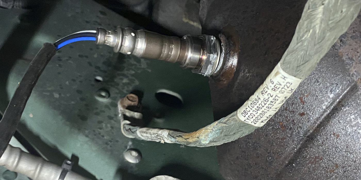
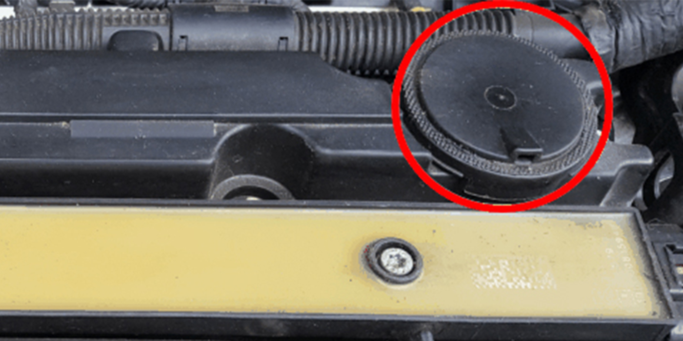
When replacing a catalytic converter with an aftermarket unit, be aware that some aftermarket units may not meet state requirements, such as those in California (Photo 1). In other cases, the aftermarket unit may not resemble the original (Photo 2), but will fit the application. In most applications, an aftermarket converter won’t last as long as the OE 8/80 converter, but will provide a cost-effective repair suited to most customer needs.
 EFFICIENCY FAILURES
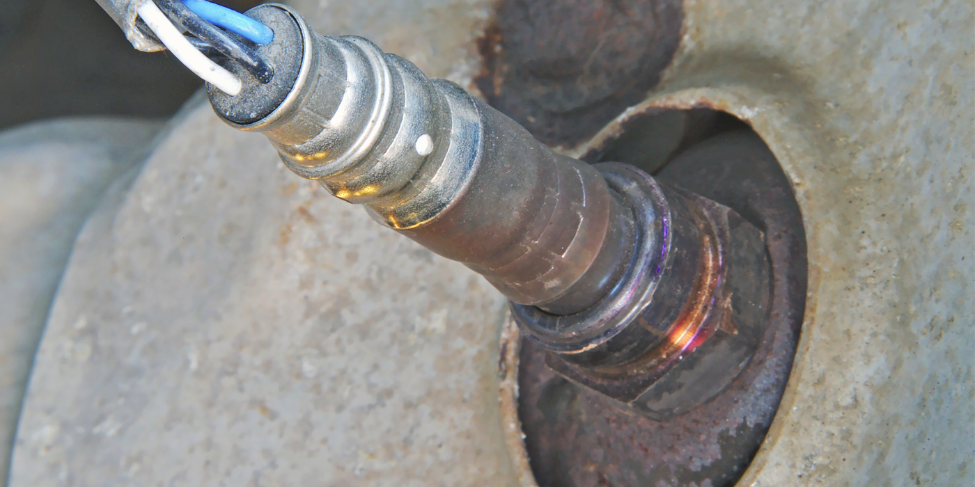
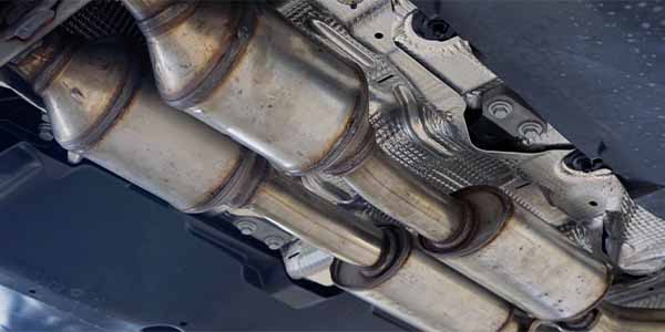
In essence, an ignition misfire can introduce a mixture of HC and O2 into the exhaust stream, which must be oxidized by the catalytic converter. Normal internal converter operating temperatures now range between 1,200 and 1,500° F. Excessive amounts of fuel being oxidized in the converter will cause operating temperatures to exceed 1,900 to 2,500° F, which may cause the monolith to melt and disintegrate (Photo 3). Keep in mind that extra fuel alone won’t increase catalytic temperatures because no oxygen is available to complete combustion.
 To prevent ignition misfire, auto manufacturers specify ignition system maintenance intervals. Some intervals are as short as 30,000 miles or as long as 100,000 miles, depending on the type of ignition system and spark plugs being used. Some manufacturers have gone so far as to incorporate misfire detection strategies, which will disable the fuel injector on the misfiring cylinder to prevent fuel from entering the exhaust stream.
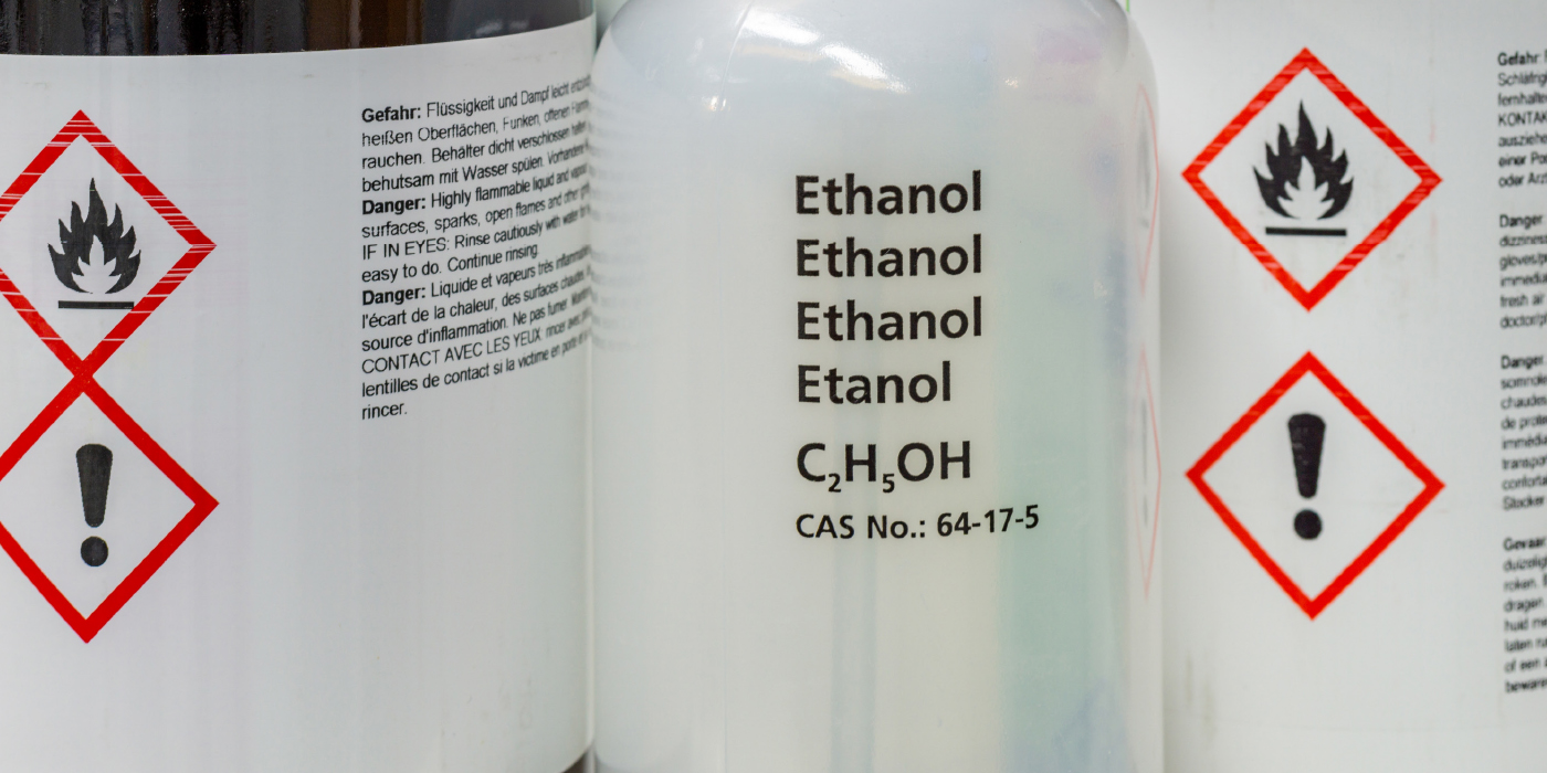
Converter efficiency can also be ruined by the presence of ethyl lead or sulfur in the fuel, and phosphorous or zinc in the motor oil. Leaded gasolines designed for off-road racing or oils designed for diesel or off-road racing applications should never be used in emissions-compliant engines. Silicon ingested into the intake from some RTV silicone gasket compounds may also reduce catalyst efficiency.
THE EXHAUST EFFICIENCY MONITOR
The enabling criteria for catalyst monitors are very application-specific. The enabling criteria might include data such as vehicle speed, engine air flow, speed and load. In addition, any emissions-related trouble codes stored in the PCM’s diagnostic memory may prevent the catalyst monitor from running. Many “global” or “generic” scan tools or scan tool modes will indicate the readiness of the catalyst monitor to run.
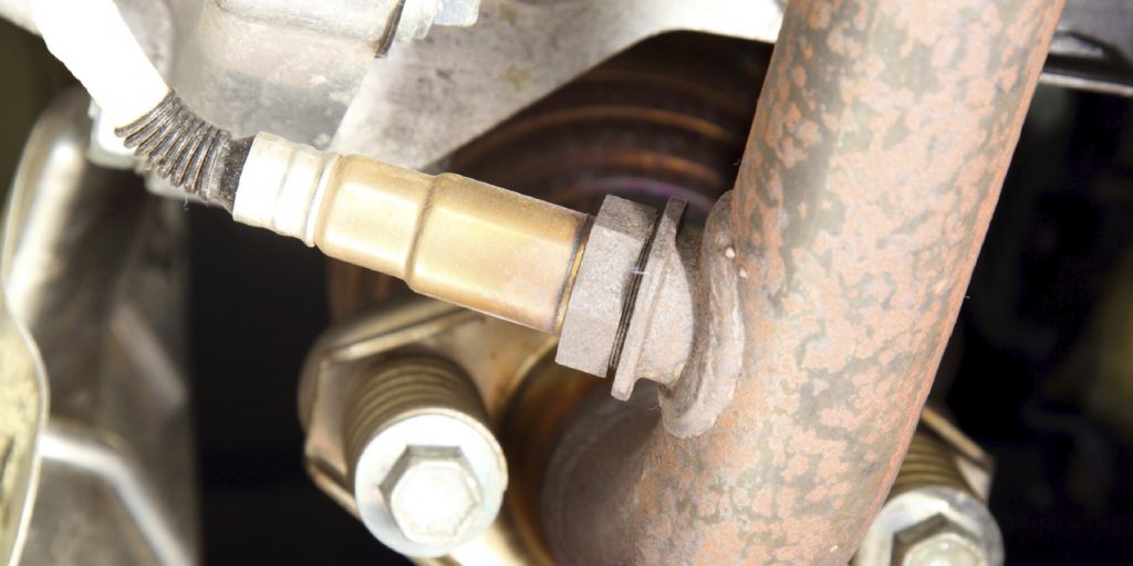
Since the three-way converter stores and releases oxygen into the exhaust stream, OBD II diagnostics use pre- and post-catalytic oxygen sensors to monitor converter efficiency by measuring the oxygen storage capacity of the converter. For this reason, exhaust leaks can upset the catalyst monitor by allowing ambient oxygen to enter the exhaust stream and distort data fed to the PCM. Exhaust leaks may cause a false failure code, conceal a failing catalyst or prevent the catalyst monitor from running.
Because the standard zirconia oxygen sensor is relatively slow to react to changes in the air/fuel ratio, the PCM switches the air/fuel ratio from slightly lean to slightly rich (from about 0.2 to 0.8 volts) during the fuel-metering process. A cold or inefficient catalyst will produce a downstream oxygen sensor voltage that more clearly mirrors the activity of the upstream oxygen sensor voltage. A good three-way converter will stabilize oxygen levels in its downstream gases, which causes the post-cat oxygen sensor to stabilize between 0.5 and 0.7 volts, indicating that about 95% of potential exhaust pollutants are being converted into acceptable compounds.
With that said, the PCM’s on-board diagnostic process is much more complex. Before running the catalyst monitor, the PCM must verify the operational status of the oxygen sensor and other sensors. In some applications, the PCM also uses the downstream oxygen sensor to verify fuel trim status or to act as a default oxygen sensor if the upstream oxygen sensor fails. In short, the PCM monitors catalyst efficiency through a complex computation of voltage signals indicating oxygen sensor and catalyst efficiency.
Most recently, manufacturers have begun using air/fuel ratio or “broadband” sensors to measure air/fuel ratio. Air/fuel sensors produce a constant voltage and can be diagnosed only through the on-board diagnostic criteria applied by the PCM. Consequently, and despite some teachings to the contrary, the PCM is the final arbiter of catalyst efficiency.
THE P0420 TROUBLE CODE
When data from the upstream and downstream oxygen sensors indicate that exhaust emissions levels are exceeding 1.5 times the FTP standards, the PCM stores a P0420 (Bank 1 catalyst efficiency below threshold) or P0430 (Bank 2 catalyst efficiency below threshold) diagnostic trouble code. In brief, it’s important to avoid jumping to the conclusion that the catalytic converter is defective.
In some cases, carbon from an over-rich fuel mixture or coolant from a leaking cylinder head gasket might temporarily coat the oxygen sensors or the converter monolith. In these cases, the converter might clear itself and provide thousands of extra service miles. In other cases, the contaminated converter may require replacement if the vehicle fails a current emissions inspection.
It’s also important to consult service data and technical service bulletins before making a replacement decision. For example, some import manufacturers require that no other DTCs (especially oxygen sensor or engine misfire trouble codes) be stored in the diagnostic memory. Some manufacturers might require that the PCM be reprogrammed to install a new set of failure parameters for the P0420 and P0430 DTCs. Unless some evidence exists to indicate that the monolith is disintegrating, such as excessive exhaust backpressure, some technicians might prefer to erase the P0420-430 DTCs to allow the converter to clear itself of potential contaminants. If the converter is covered by the 8/80 warranty, trouble codes should be left in the diagnostic memory to help the dealership technician assess the problem.
Keep in mind that the OBD II catalyst monitor requires a specific set of driving conditions to occur before the on-board catalyst test or monitor begins. In any case, catalyst diagnostics must be approached in a methodical manner to ensure that the root cause of the dreaded P0420-430 DTCs is resolved.