“My dash lights up like a pinball machine, the engine loses power for a few seconds, and then seems to run OK.” Although I’d actually been chasing this Diagnostic Dilemma for the better part of a year, this four-wheel drive 2001 Blazer equipped with the 4.3L Vortec engine and manual transmission otherwise appeared to be in good overall condition.
Six months earlier at 140,000 miles, I had replaced the fuel pump to correct a marginal fuel pump pressure problem. Prior to this, I attributed his “pinball machine” instrument panel complaint to a momentary engine stall caused by a weak fuel pump. As with many General Motors products of this vintage, I’d also replaced the fuel pump connector and relay to ensure against future failures, and had also cleaned and inspected all power and ground connections to address an intermittent charging system problem indicated by the instrument panel voltmeter. Future needs included replacing a weak battery and a sticking coolant thermostat.
As time went on, the glaring instrument warning lights and momentary loss of power complaint became more frequent. Another code check revealed a laundry list of diagnostic trouble codes (DTCs). Of course, neither the thermostat nor the battery had been replaced, so I explained to my friend that, without the engine reaching specified operating temperature, and with the weak battery, I could not accurately diagnose the root cause of his complaint. In fact, he was thinking that the new fuel pump was defective. Since I had installed an original equipment (OE) fuel pump and had verified its amperage waveform afterward, I didn’t agree. And besides, how could a bad fuel pump create as many as 11 different DTCs? A few months and many occurrences later, my friend reluctantly agreed to let me diagnose his instrument cluster and momentary loss of power complaint.
FINDING A DIAGNOSTIC DIRECTION
It could obviously take days to duplicate this month’s Diagnostic Dilemma. And, like many of these random occurrences, even if I duplicated the complaint, I had no means of gathering data other than retrieving the laundry list of DTCs contained in the PCM’s diagnostic memory. More important, my owner friend re-emphasized the apparent charging system problem as indicated by a low voltage reading on the instrument panel voltmeter.
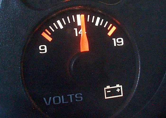
With that fact in mind, I connected my digital multimeter (DMM) to the dash panel accessory power outlet, which is directly connected to B+ voltage. Upon starting the engine, I noticed approximately 13.2 volts on the instrument cluster voltmeter and 14.2 volts at the DMM. While an inaccurate instrument cluster voltmeter isn’t a new experience, I jotted that bit of information down for future reference. A quick fuel pressure test revealed 60 psi key-on, engine-off regulated pressure at the fuel pump with plenty of volume.
At this point, I also polled all modules and recorded all trouble codes. The PCM contained a P0128, P0230 and P0654. Of particular interest was the P0230 DTC, which relates to the fuel pump relay control circuit to the PCM. Last, the P0654 indicated a circuit open or short-to-ground on the tachometer circuit. Other PCM DTCs included P0449 (evap ckt low), P0103 (MAF ckt high), P0135 (B1S1 oxygen sensor heater ckt), P0138 (B1S1 signal high), P0418 (air pump relay ckt fault), and P0443 (EVAP purge ckt fault). Last, a U1064 bus communications DTC was stored in the body control module (BCM).
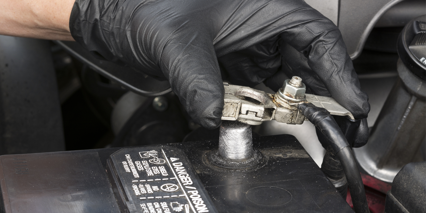
Of course, the P0128 indicated that the thermostat might be bad, but I verified the replacement by measuring the coolant outlet temperature. At this point, a re-test indicated that the battery condition had deteriorated. As I’ve said many times in this column, voltage testing can’t be accurately done if the battery is dying or if the dead battery is boosted with a battery charger. So, I installed my known-good shop battery to eliminate what I call, “The Stupid Stuff.”
PRIORITIZING THE DTCs
At this point, it’s unlikely that the Blazer had developed multiple problems in so many separate operating systems. I began by prioritizing a total of 11 different DTCs, beginning with four engine sensor input DTCs. Of course, the P0128 might have been stored before the thermostat had been replaced.
The three remaining relevant sensor DTCS includeD P0654 (tachometer), P0103 (MAF), and P0138 (B1S1 oxygen sensor signal). Since the tach, MAF and oxygen sensor signals are relayed to the PCM
But more important were the DTCs having to do with relay operation including P0230 (fuel pump relay), P0418 (air pump), P0449 (evap), and P0443 (evap purge). Obviously, while each DTC represents a separate circuit, all are supplied control voltage by the ignition switch and all are pulled to ground by the PCM. Clearly, the PCM was operating at the time of failure or it shouldn’t have stored all of these relay-related DTCs. Of course, this begs the question of a voltage drop through the ignition switch, which might tend to starve each of these relays for control voltage., I chose for the moment to ignore these three sensor DTCs and the U1064 bus communications DTC as well.
GM IGNITION SWITCHES
Although the topic of General Motors ignition switches has recently been a staple of the news media, these issues have revolved around a weak detent in the switch mechanism that allows the switch to vibrate from the “on” position to the “off” position. If the vehicle is involved in an auto accident, the air bags will fail to deploy if the switch jiggles to the “off” position, which can seriously injure the driver and occupants.
But, in past renditions of Diagnostic Dilemmas, I covered several automatic transmission failures caused by faulty ignition switches in the ’90s vintage GM pickup trucks. I quickly learned that, if I retrieved a laundry list of transmission-related DTCs, I’d test the available voltage at instrument panel fuse No. 20.
If the fuse had less than battery voltage, a worn switch was indicated. In most cases, fuse No. 20 tested at around 9.0 volts, which is a clear-cut case of insufficient circuit voltage to operate the transmission valve body solenoids. But past that, I’d never put together a more comprehensive method for diagnosing a worn ignition switch.
BUILDING A DIAGNOSTIC STRATEGY
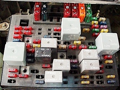
Whereas in years past, fusible links protected all high-amperage B+ circuits, modern vehicles protect these same circuits with high-amperage “Maxi” fuses found in an underhood fuse box. The underhood fuse box also contains various “mini” fuses that protect various powertrain system operating circuits as well as relays that activate mechanical functions like the fuel pump and evaporative system. For this reason, the underhood fuse box provides an excellent location for performing non-intrusive voltage testing on all major circuits.
As for the fuses powered by the ignition switch, the 15-amp Eng “1” fuse powers the MAF sensor, evap purge and vent solenoids. The 15-amp Vehicle Control Module 1 (VCM “1”) fuse powers the VCM, crankshaft position sensor, ignition system and fuel injectors. The 20-amp VCM “B” fuse powers the VCM, fue pump and oil pressure sensor.
In theory, I should’ve been able to place a test probe on B+ (Ignition “A”) and test for voltage drop through the ignition switch by probing the Eng1, VCM 1, and VCM “B” fuses with the engine running to maintain constant voltage and electrical load. After the engine warmed up, B+ dropped from 14.2 volts to 13.9 volts (as it should) to compensate for a normal operating temperature increase. The voltage difference between Ign “A” and Eng “1,” VCM “1,” and VCM “B” fuses was 12.7 volts, 12.8 volts and 12.5 volts, respectively. An additional test at No.1 4 fuse in the i/p fuse box, which powers the i/p gauges and body control module (BCM), indicated a similar voltage drop. In short, I was seeing about a 1.34-volt drop between Ign “A” and Eng “1,” VCM “1,” and VCM “B” fuses and i/p fuse No. 4, which indicated that a voltage drop was indeed occurring through the Blazer’s ignition switch.
LESSONS LEARNED
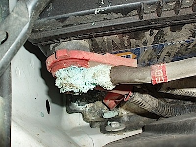
Most veteran diagnostic techs know that multiple, often unrelated, DTCs are usually caused by a power or ground problem. In this instance, I had previously inspected, verified and cleaned all of the B+ and B- connections. For a while, I suspected that worn alternator brushes were causing the intermittent low-voltage condition at the instrument panel voltmeter. But the alternator brushes should have eventually failed, but didn’t. This, of course, left the ignition switch as the most likely source of the low-voltage condition that was causing multiple DTCs to store in the PCM’s diagnostic memory. From previous experience with GM products, I also knew that bus communications “U” codes, in this case DTC U1064, would likely be stored if the ignition switch was defective. At this point, the battery was the only item replaced. The only parts removed for diagnosis were the underhood fuse box and instrument panel fuse box covers.
THE FINAL TEST
Four months out, the random Pinball Effect and momentary loss of power complaint this 2001 Chevy Blazer hasn’t reappeared. The only new issue is a problem with the transfer case electronics, which appeared only after the new ignition switch was installed. In this instance, the “transfer case service” warning light turned on and a DTC indicating a mode switch failure appeared, which is a very common problem on GM trucks. Replacing the mode switch revealed a no-code, non-engagement problem with the front axle vacuum solenoid and vacuum lines. With the onset of winter, I replaced both, which tied up the loose ends of this diagnostic dilemma.