Wheel speed sensors (WSS) provide essential wheel speed information not only for anti-lock brake systems (ABS), but also for traction control and stability control systems. Some vehicles even compare the wheel speed sensor readings against the vehicle speed sensor (VSS) to make sure all of these sensors are accurate and working correctly.
In some situations, it is also possible that the signal from a WSS may not be bad enough to set a fault code, but may be off enough to upset the normal operation of the ABS, traction control or stability control systems. This might be the result of an intermittent signal or a noisy signal that is confusing the system control module.
On older ABS systems, a fault code is typically set if there is a loss of a signal in a WSS circuit (shorted or open), or the reading from one WSS sensor differs significantly from the rest. On some newer vehicles, “plausibility” codes may also be set if the speed reading of any WSS sensor differs from the vehicle speed sensor by more than 3 to 5 mph.
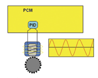
Most scan tools will allow you to not only read and clear the ABS codes that have turned on the ABS warning light, but to also look at the individual WSS inputs (Performance Information Data or PIDs). The scan tool will display a speed input in miles per hour (mph) for each wheel speed sensor.
 WSS SPEED INPUTS
Most wheel speed sensors (except for the latest generation of “active” WSS sensors) won’t generate a readable signal until a vehicle is traveling 3 to 5 mph or faster. You can spin each wheel by hand to see if the WSS is generating a signal, but that won’t tell you if the signal is accurate or how one WSS compares to another. So to check the WSS inputs, the vehicle needs to be driven in a straight line at 12 to 25 mph while you or a helper watches the wheel speed sensor PIDs on the scan tool.
If all of the wheel speed sensors are generating a speed signal, and they all agree, the fault is not a bad WSS, but something else (possibly an intermittent wiring fault in one of the WSS circuits). Since most WSS problems are due to broken wires or loose or corroded wiring connectors, visually inspect the wires and use an ohmmeter or continuity tester to check the wiring while wiggling the wires back and forth. If the circuit suddenly goes open or shows a jump in resistance, you’ve found the fault.
If one of the WSS PIDs reads zero mph and the other three are reading vehicle speed, the fault is a bad sensor or a fault in the sensor wiring circuit (keep reading for information on how to check the sensor itself).
If all four WSS are indicating a speed reading, but one is reading a couple of mph faster than the others, stop the vehicle and check the tire size on the wheel that is reading faster than the others. Chances are somebody mounted a tire that has a smaller diameter than the others. If the front WSS sensors are both showing a different speed than the rear WSS sensors, this too may be the result of someone having replaced the OEM tires with ones that are a different size front and rear.
Changing tire sizes will change the WSS inputs, which may upset the operation of the ABS, traction control or stability control systems. On some vehicles, the control module can be reflashed to accommodate a change in tire size. But on most vehicles this is not possible. So the vehicle owner has to stick with the same OEM tire and wheel size. If they want to replace their OEM wheels and tires with aftermarket wheels and tires, they can go with plus wheel sizing and lower profile tires to keep the overall tire diameter the same as before.
If you find a single WSS that is reading slower than the others, the cause may be one of two things: an oversized tire on that wheel or the sensor is not generating a pulse for every notch in the tone ring causing a lower than normal speed output. Things to check for here (besides the tire size) would be rusty, corroded or damaged teeth on the tone ring, or an excessive air gap between the tip of the sensor and the ring.
WSS CHECKS
Whether you have a scan tool or not, there are a number of checks that can be made to verify the operation of a wheel speed sensor.
The wheel speed sensors on most vehicles are magnetic and generate an alternating current (AC) signal that increases in frequency and amplitude with wheel speed. These are sometimes called “variable reluctance” (VR) or “passive” WSS sensors because they generate their own voltage signal when the vehicle is in motion. They have two wires: signal and ground.
Inside a passive WSS sensor is a permanent magnet core surrounded by copper wire windings. When the teeth on the tone ring rotate past the sensor tip, it changes the magnetic field and induces a current in the sensor windings. The result is a classic sine wave current pattern that changes with wheel speed.
The strength of the signal can be affected by resistance inside the sensor, resistance in the external wiring and connectors, metallic debris from worn brake rotors, drums or semi-metallic brake linings sticking to the end of the sensor, and the air gap between the sensor and tone ring (which is mounted on the axle, CV joint, brake rotor, brake drum or inside the hub).
A narrow air gap is usually necessary to induce a strong signal in the sensor’s magnetic windings. Air gaps typically range from .016 in. to as much as .050 in. (0.40 to 1.3 mm) depending on the application. As a rule, there should be no more than .006 inches of runout in the tone ring because too much runout may cause an erratic signal. A cracked tone ring can also cause an erratic signal.
With magnetic WSS sensors, you can check the integrity of the sensor by connecting an ohmmeter across its terminals. The resistance specs will vary depending on the application, but most sensors should read 450 to 2200 ohms (always look up the exact specifications because they can vary a great deal from one vehicle application to another). If a sensor reads open, shorted or is out of specifications, it can’t generate an accurate signal and must be replaced.
You can also test the sensor’s output by spinning the tire by hand at a rate of about one revolution per second. With a voltmeter attached to the sensor’s terminals, a good WSS sensor should generate about 50 to 700 millivolts AC.
If a sensor’s output is low, and the sensor is removable, pull it out and clean the tip. Also, check the air gap when the sensor is installed (refer to the vehicle manufacturer’s specifications and adjustment procedure).
If you have a digital storage oscilloscope, you can connect the leads to the WSS sensor terminals and observe the waveform on the scope. A scope will show the voltage and frequency of the signal, as well as any missing or distorted humps in the sine wave pattern. If one or more humps in the wave pattern are significantly shorter than the others, it indicates one or more damaged teeth on the sensor tone ring.
The amplitude of the signal is affected by the air gap between each tooth and the sensor, so if a tooth is chipped it won’t generate as strong a pulse as the other teeth. The fix would be to replace the damaged tone ring (or the hub if the sensor and tone ring are integral parts of the hub assembly).
Something else to watch out for is mismatched parts. To produce an accurate signal, the sensor’s tone ring must have the correct number of teeth for the application. Make sure the tone ring on a replacement rotor, drum, axle shaft or outboard CV joint is the same as the original if any of these parts have been recently replaced, or need to be replaced.
ACTIVE WSS SENSORS
In recent years, several new types of “active” WSS sensors have appeared. These are used on many 1999 and newer Chrysler, Jeep and Mercedes models with Teves Mark 20e and up Teves ABS systems. Active WSS sensors are also found on the Ford Focus, Toyota Tundra and other applications. This type of sensor is becoming more common on late-model vehicles because of its greater accuracy at low speeds.
Active WSS sensors, which Chrysler refers to as “magneto-resistive” sensors, work like a “Hall effect” sensor and generate a square wave on-off digital signal that changes frequency with wheel speed. This type of sensor detects the change in magnetic polarity (flux) as the teeth on the tone ring or small magnets pass under it. Small magnets may be built into the wheel bearings or bearing seal for the WSS sensor to read.
Active sensors often have three wires: a voltage reference input (5 to 12 volts), a signal output and ground. But some active sensors have only two wires (reference voltage and signal return).
How can you tell a 2-wire active sensor from a 2-wire passive sensor? Turn the ignition on and backprobe both wires with a voltmeter. If you see a voltage reading (5 to 12v), you have an active WSS sensor. If you see no voltage (0v), you have a passive WSS sensor.
Active WSS sensors also have an integrated circuit within the sensor itself that converts and amplifies the signal before it goes back to the control module. This allows the sensor to read wheel speeds all the way down to zero mph (which improves ABS control at low speeds as the vehicle comes to a halt).
When the key is on, an active WSS sensor has two states: low and high. In the low state, it generates a fixed 0.9 volt return signal of about 7 milliamps. In the high state, it generates a signal of 1.65 volts and 14 milliamps. The rate at which it toggles back and forth between its high and low states corresponds to the speed of the wheel.
This type of sensor must be connected to its wiring harness to test it, and the ignition key must be on so the control module can provide reference voltage to the sensor. If you forget and leave the key off, you won’t get any output from an active WSS sensor.
Because of the added electronic circuitry inside the sensor, and active WSS sensor cannot be tested with an ohmmeter like a passive WSS sensor. You have to look at its output signal when the wheel is turning and the ignition is on. This can be done with a scan tool (look for a mph reading while spinning the tire or during a test drive), with a voltmeter (turn the wheel very slowly and look for a change in the voltage output from high to low), with a NOID light (the LEDs on the NOID light will flash when it detects a signal pulse), or a DSO. The waveform on the scope should show a square wave pattern that changes from low (0.9v) to high (1.65v) as the wheel turns. The difference in height of the waveform should be 0.75 volts (1.65v minus 0.9v).

