I occasionally feel like I’m trying to solve a jigsaw puzzle that has a few extra pieces. You know the feeling, the puzzle is complete, but you see an extra diagnostic trouble code (DTC) or two that doesn’t make sense. As diagnostic technicians who need to know the answers, we pursue these extra pieces of the diagnostic jigsaw puzzle with plenty of time and passion. And, we do this in the hope that the next time around, we’ll develop a better approach to solving the problem at hand. With that said, let’s look at a single-code problem on a 1998 Chevy S-10 pickup with the 4L60-E automatic transmission and 271,000 miles on the odometer.
NO POWER WHEN COLD
This problem was referred to me by my local transmission shop. The elderly owner’s complaint was that the S-10 “accelerated kind of slow when cold.” Further questioning revealed that, after the transmission warmed up and the ignition was cycled off/on, the S-10 would accelerate normally. I took the S-10 for a test drive and, sure enough, it was starting from a dead stop in 3rd gear, which explained the lack of acceleration. Returning to the shop, I retrieved a P0758 DTC, indicating a problem with the 2-3 shift solenoid or solenoid circuit.
ENABLE CRITERIA
As with most applications, the vehicle control module (VCM) controls the 2-3 shift by grounding the 2-3 shift solenoid through VCM circuit #1223. When the VCM detects a continuous open circuit or continuous short-to-ground in the 2-3 shift solenoid circuit, it sets DTC P0758, which is a one-trip code. The enable criteria are: 1) system voltage is at least 10-16 volts, 2) engine speed exceeds 450 rpm for 5 seconds, 3) the system is not in fuel cutoff mode, 4) the VCM commands the solenoid “on” and input voltage remains high, 5) or the VCM commands the solenoid “off” and input voltage remains low. When P0758 is set, the MIL illuminates, maximum line pressure is commanded and torque converter clutch engagement is inhibited. Moreover, the VCM turns off the MIL after three consecutive trips with no failure. Turning the ignition off long enough to deactivate the VCM will restore normal shifting, providing the electrical problem no longer exists. Nothing mysterious here, because all the pieces fit into our diagnostic jigsaw puzzle.
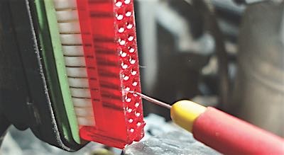
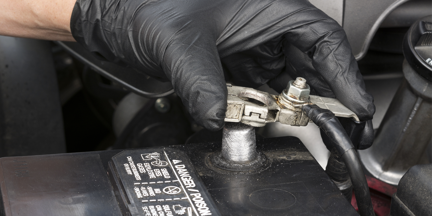
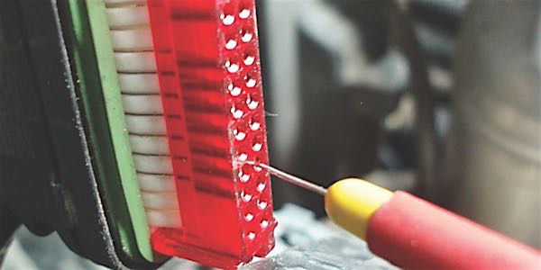
Moving from the edges to the center of our jigsaw puzzle, the diagnosis of P0758 is very straightforward: 1) Disconnect battery B- and VCM connector C2; 2) Measure resistance through the 2-3 solenoid by attaching one ohmmeter lead to the B+ cable at the underhood fuse box and the other to the VCM C2 connector pin #4. This method completes a circuit from B+ to VCM C2 pin #4, which activates the 2-3 shift solenoid when grounded; 3) This 2-3 solenoid measured 4.4 ohms at about 50º F, with the specification being 19-31 ohms at a room temperature of 70º F.
So, why did the 2-3 solenoid work when warmed up? Answer: Circuit resistance increases with temperature. Although the 4.4-ohm cold resistance was completely out of the specified 19- to 31-ohm range, any spool-wound circuit can heat up very rapidly. Once past a specific temperature threshold, the VCM would “see” the 2-3 shift solenoid as operating through a normal range of voltage and resistance and begin to shift normally.