The Gates Technical Team has recognized applications for potentially difficult timing belt installations. Industry publications as well as professional technician forums may recommend the use of only an OES replacement timing belt due to a “perception issue.” Standard concerns state that the aftermarket belt is too long, doesn’t look or feel like the one purchased from the OE dealer and will generally lead to an illuminated malfunction indicator lamp (MIL). This Gates technical service bulletin explains the common installation errors that can lead to this misperception.
After performing timing system maintenance, technicians occasionally report issues of cam sensor-related codes. Often, the assumption is that these codes are caused by the timing belt, but in the case of the Gates T257 timing belt, this assumption is false.
The Gates T257 timing belt meets the original equipment manufacturer’s dimensional specifications. In fact, Gates was the OEM supplier of this particular belt as well as the original OES supplier. The Gates T257 maintains the exact dimensional specifications as the OE belt. Our technicians have identified common installation issues with respect to timing system and water pump maintenance.
The following are potential problems encountered during the setup of the timing belt.
› Cam sprockets were swapped from right to left, reversed or scratched
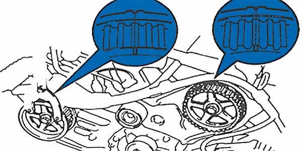
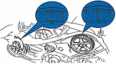
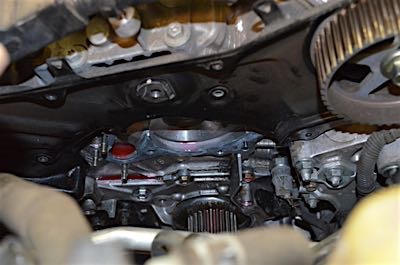
› Improper alignment between timing belt and crank cam on rear cylinder bank
be performed with the aid of a mirror.
The most common cause found with immediate illumination of the MIL associated to cam sensor codes has been misalignment between the rear cam gear and timing belt. Illumination of the MIL will occur with the cam being one tooth advanced or retarded.
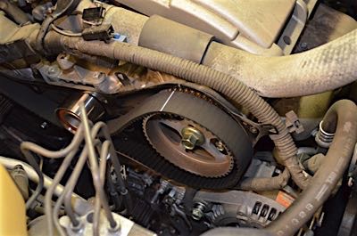
Gates always recommends replacement of the water pump assembly combined with a complete flush of the cooling system when performing timing system maintenance. Removal of the upper rear cam gear cover is unnecessary in order to R&R the water pump unless cam seal renewal is also being performed.
NOTE: Do not interchange or mix cam gears if they are removed — ensure they are kept in appropriate order (right vs. left and front vs. rear).
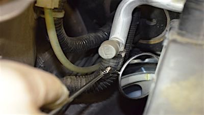
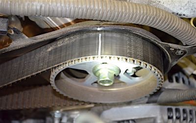
Cautions on related system components would include verification of the upper idler pulley operation. Due to the step design within the pulley, it is possible to secure this component at an improper angle. Ensure the idler pulley is operating within the same system plane and that the timing belt is tracking in the center of the bearing.
Courtesy of Gates.