Does performing a pad replacement on a Toyota Prius scare you? Well it should; if you treat it like every other vehicle. But, if you know a few things ahead of time, the job can be performed like any other brake job.
Do not worry about high voltage. Worry about angry customers due to comebacks because the brake/ABS light is on. Servicing a Prius does not require many special tools to perform a front brake pad replacement. Just normal hand tools are required and maybe a scan tool and software that can read chassis codes if you are unlucky or have to replace hydraulic components. But, it is possible, according to Toyota, to replace pads without a scan tool.
There are three basic concepts that technicians must be aware of before they push back the pistons on the front calipers. First, the most important basic aspect to grasp for any technician is that the Prius braking system has pressure sensors at the master cylinder and the outputs for wheels. These sensors check the pressure and any anomalies between the two pressures will cause a trouble code to be set.
 Second, when the driver is pushing on the brake pedal, it might not be producing hydraulic braking force at the wheel. The system is measuring the stroke and pressure generated at the brake pedal and translating that into braking force created by a generator. The system is not a full-time brake-by-wire system. Hydraulic brakes are used during hard stops and at speeds below 10 mph. When the regenerative braking is engaged, it will give the driver feedback with a device called the “stroke simulator.”
Last, even if the engine is off and the car is not moving, there is still hydraulic pressure in some of the lines. The Prius can drive without the internal combustion engine running. Also, even if the car is in park without the engine running and the keys in the ignition, the engine may start to charge the battery or run the HVAC system. The keys need to be out and away from the vehicle during service. If you keep these concepts in the back of your mind, you should be able to perform any brake service with the right tools.
Prius Models
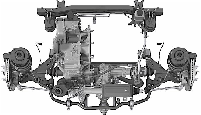
The Prius was introduced in 2001. The rotor and caliper are the same as the Echo, Scion Xa/Xb and MR2. In 2004, Toyota changed the brake system when it upgraded the batteries and electric motor. The most distinctive difference is the lack of a vacuum brake booster. In 2004, a different ECU and larger accumulator and pump now provided the boost.
At the wheel, the system stayed the same in regard to the rotor and caliper. But, the brake pad characteristics were changed for better longevity and corrosion resistance.
At the rear are drum brakes without any regenerative braking. The rear drum brake is almost bullet-proof. But, there have been some problems with the emergency/parking brake cables and the electric motor that actuates the system. In TSB BR002-07, it outlines how to resolve problems with the brake light staying illuminated after the emergency/parking brake has been disengaged. This procedure will require a scan tool
The Pads
It is not uncommon to find a Prius with 70,000- or 100,000-miles with the original set of pads. This is due to regenerative braking creating the majority of braking force. But, this does not mean that other components, like hardware and rubber seals/boots, can’t fail sooner.
The Prius has unique requirements for the brake system. On 2001-2004 models, the hydraulic brakes were not used until the vehicle was below 7 mph or if the vehicle had to make a hard stop.
The majority of the time, the pads never reached conventional operating temperatures and corrosion could occur between the backing plate and friction material due to the fact that the pads never dried out. On some vehicles, the corrosion between the friction material and backing plate would cause a complete separation.
Always use a high-quality pad for the Prius and other hybrid applications to avoid problems. It is not a question of better performance. It is a question of quality and engineering.
Since it is impossible to perform a conventional break-in/bedding procedure on the test drive, make sure the manufacturer promises excellent performance right out of the box. Also, applying a non-direction finish with a ball hone will help the new pads evenly deposit a layer of friction material to the new rotor.
The Prius use a two-part shim. The solid piece is the anti-noise layer. The perforated part provides lubrication and acts as a bearing. The two shims’ contact areas float on the lube and slide during application. Always replace the shim and do not reuse an old shim!
Rotors
There is nothing special about servicing the rotors on this vehicle. But, if you are planning to use an on-the-car brake lathe, make sure the system is off for two minutes. Most on-the-car brake lathes operate below the speed threshold of the generator’s ability to generate voltage.
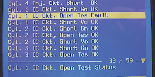
Rotors that have excessive runout or thickness variation can cause hydraulic pulsations in the brake circuit. These irregularities can cause the pressure sensor to trigger trouble codes C1341 thru C1344 that indicate a hydraulic circuit malfunction.
Hydraulic Components If you have to replace a caliper, wheel cylinder or brake hose, you must have a scan tool that can clear codes and operate the ABS pump during bleeding. Manual or “one man” bleeding will not work on this vehicle due to the valves and solenoids that manage the regenerative braking. Also, the system must be deactivated to prevent damage the components. Also, read all of the precautions in the service information before attempting to replace any hydraulic component.
Brake Pad Replacement
- Lift the car and remove the wheels.
- If work that does not involve brake fluid bleeding, such as disc brake pad replacement, is started two minutes or more after the power switch is turned off, brake control (ECB) prohibition/deactivation is not necessary.
- Remove the two bolts and lift the front disc brake caliper from the pin slides. Make sure that you have a thin 17mm wrench to get at the bolt hex on the inner part of the slide pin. Secure the caliper to the strut with a hook or strap.
- Remove the pads and inspect the friction material for glazing, corrosion, edge lift or other mechanical damage. Using a ruler, measure the pad lining thickness from the base of the backing plate to the friction surface. Also, make sure the inside and outside pads are evenly worn.
- Standard thickness: 11.0 mm (0.433 in.).
- Minimum thickness: 1.0 mm (0.039 in.).
- Remove the two anti-squeal shims from the pads.
- Remove the caliper brackets. Inspect the surfaces for corrosion and mechanical damage.
- Remove the slide pins, dust boots and pad abutment clips from the caliper bracket. Clean the bracket with brake cleaner. Make sure to remove all of the old grease from the slide pin holes.
- Check the looseness of the front wheel bearing and runout in the axle hub before removing the rotor. Hold the front disc with the lug nuts (torque: 103 Nm or 76 ft/lbs).
- Using a micrometer, measure the rotor’s thickness in at least six areas.
- Standard thickness: 22.0 mm (0.866 in.).
- Minimum thickness: 20.0 mm (0.787 in.).
- Standard thickness: 22.0 mm (0.866 in.).
- Check for runout by holding a dial indicator 10 mm away from the outer edge of the rotor. Maximum disc runout: 0.05 mm (0.0020 in.). Before removing the rotor, mark the high and low points of runout. Also, mark the rotor’s position on the hub. If you do this, you can change installation positions of the rotor and axle so that the runout will be reduced. After the rotor has been removed, measure the runout in the face of the hub and mark the high and low points.
- Machine the rotor with either a bench or on-the-car brake lathe.
- Install shims on the new brake pads. If you are using original-style shims, apply high temperature disc brake grease to the area where the anti-squeal shim No.1 makes contact. Install the two anti-squeal shims No. 1, and the two anti-squeal shims No. 2 to the front disc brake pads.
- Install the caliper support brackets with the two bolts. Torque: 109 Nm, 81 ft/lbs).
- Install front disc brake cylinder slide pin. Toyota recommends lithium soap-base glycol grease. Push the front disc brake cylinder slide pin into the dust boot and install it. Make sure the dust boot’s seals are in the grooves on the pins.
- Install the abutment clips on the lands of the caliper bracket. A high temperature, brake specific grease can be used on the surfaces the make contact with the tabs or ears of the pads. Apply only a very light coating.
- Install the pads in the caliper brackets. Toyota advises that the supports (abutment clip) have sufficient rebound when installing the pad. Also, check that the pad does not have too much play after installation. This can lead to brake drag and increased fuel mileage.
- Gently push in the caliper piston only enough to fit over the new pads and shims. Toyota says that it is not necessary to crack the bleeders during this procedure and doing so could cause more problems than it solves. If you feel comfortable blocking the brake hose and cracking the bleeders to remove displaced brake fluid, it can be done this way. See TSB BR0012 for more information.
- Install the brake calipers. Torque: 34 Nm or 25 ft/lbs).
- Install front wheels. Torque: 103 Nm or 76 ft/lbs)
- With the car still powered down with the key out of the ignition, stroke the pedal several times to bring the pads in contact with the rotor.
- Check fluid level in the reservoir. Adjust the brake fluid level to the MAX line with the power switch on (IG). The brake fluid level must be adjusted to the MAX line.
- Test drive the vehicle. Make sure that you perform several stops to 0 mph and at least one hard stop. If the ABS warning light does not come on, you are finished. If an ABS light does come on, you will need to perform some additional steps.
 If you are replacing calipers or other hydraulic components, you will have to deactivate the system with a scan tool. Most scan tools will walk you through the process that involves removing the two ABS pump relays and pumping the pedal in a sequence to depressurize the system. The system can also be deactivated by waiting for two minutes after turning the power switch OFF, stopping the brake pedal operation and closing the driver door before removing the two relays (see photo).
Also, it is a good practice when working on vehicles with advanced ABS and Stability Control systems to remove the keys from the vehicle and place in a different room, like at the front counter.
Do not use excessive amounts of grease that can contaminate the friction material once the brakes have been heated.
 ABS Light On?
If the ABS light did come on during the test drive, disconnecting the battery is not the way to clear the codes. Yes, it will clear some codes, but you will have to recalibrate the steering position sensor and other items, like the automatic power windows, will stop functioning.
What happened during the test drive is that the pressure sensors at the wheel detected an abnormal reading when the hydraulic system was first engaged. The system may have detected low pressure when extra fluid is required to bring the piston into contact with the rotor, or residual pressure from you pushing the piston back. DTCs may be stored if brake fluid leaks, wheel cylinder vibrates due to uneven wear of the brake disc rotor, or foreign matter enters the solenoid valve.
Toyota has issued a Technical Service Bulletin BR012-06 on the topic. It states: “When replacing the brake pads on an ECB (Electronically Controlled Brake) system equipped vehicle, retracting the caliper’s piston and installing new brake pads may cause trouble codes to set the next time the brake pedal is depressed.”
If any of the following four trouble codes are set, all the codes need to be cleared and another test drive completed to verify the code has been cleared:
- C1341 Front Hydraulic System RH Malfunction
- C1342 Front Hydraulic System LH Malfunction
- C1343 Rear Hydraulic System RH Malfunction
- C1344 Rear Hydraulic System LH Malfunction
If you do not have a scan tool, it is possible to clear the codes with Special Service Tool (SST) 09843-18040 (Basically a fancy jumper wire).
(a) Using SST, connect terminals TC and CG of the DLC3.
(b) Turn the power switch ON (READY).
(c) Clear the DTCs stored in the ECU by depressing the brake pedal eight times or more within five seconds.
(d) Check that the warning light indicates a normal system code.
(e) Remove SST.
Note: Clearing the DTCs cannot be performed by removing the cable from the negative (-) battery terminal or the ECU-IG fuse.
Conclusion
In May 2008, Toyota announced that its worldwide cumulative sales of the Prius had passed the 1 million mark. Nearly 60% of all Prius sales have been in North America where 183,800 vehicles were sold in 2007. This is a significant opportunity for shops as the age of the hybrid fleet starts to age.
You will not have to wear insulated gloves and use rubber-coated tools to work on the brake system, but you will have to arm yourself with knowledge.
PRIUS TSBs
TSB BR002-07: Parking Brake Warning Light stays illuminated after the parking brake pedal is released.
Models: 2004 –2007 Prius
Some 2004 – 2007 model year Prius vehicle customers may complain that the Parking Brake Warning Light stays illuminated after the parking brake pedal is released. The parking brake assembly, which includes the parking brake switch, has been modified to correct this condition. Use the following repair procedure to remove and replace the parking brake pedal assembly.
(Includes 2004 – 2007 model year Prius vehicles produced BEFORE the production change effective on VINs JTDKB20U#73249043 thru JTDKB20U#77632091.)
Repair Procedure
- Confirm the customer’s complaint that the Parking Brake Warning Light stays illuminated after the parking brake pedal is released.
- Check to see if the parking brake switch is loose and/or the plastic guide pin for the parking brake switch is broken. This can cause the switch to swivel out of position and NO longer make contact with the parking lever to engage the parking brake switch and open the circuit.
- Replace the parking brake pedal assembly if the condition in step 2 is found. Refer to the repair manual for the procedures for “Parking Brake Control Pedal Assembly: Overhaul.”
TSB BR002-07: Brake Actuator Noise
Covers: 2004 – 2007 Prius Some 2004 – 2007 model year Prius vehicles may exhibit a squeak-type noise when pressing or releasing the brake pedal. This noise may only be audible when the vehicle is in “READY” mode and the vehicle is not moving. Brake system performance is not affected by this noise. Use the following procedure to address this concern.
- Confirm noise condition by pressing/releasing the brake pedal.
- Bleed the brake system with a scan tool and the correct repair procedure. If the noise is NO longer present when pressing/releasing the brake pedal, the repair is complete. If the noise is still present, go to step 3.
- If the noise is still present, replace the Brake Actuator Assembly.
- Road test for proper operation.
Refer to your source of repair information for the correct procedure.