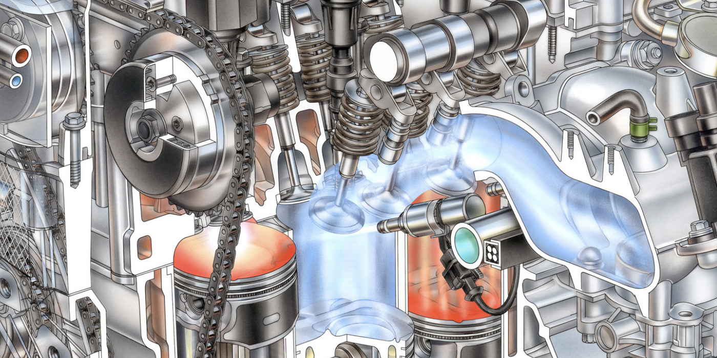
As motor vehicle technology enters a new decade, we’ll find that gasoline direct fuel injection (GDI), spark-controlled compression ignition (SpCCI), and homogenous charge compression ignition (HCCI) engines demand far more precise fuel control, which requires more complex “broad-band” air/fuel ratio (AFR) sensors that routinely monitor 22:1 and leaner air/fuel ratios.

Thanks to faster-computing engine control modules that can detect even minor malfunctions, most oxygen sensor diagnostics have become scan tool-based. Whereas we used lab scopes to diagnose rich/lean problems on narrow-range zirconia oxygen sensors in 1985, modern AFR oxygen sensor performance data is numerically displayed on scan tools.
CATCHING A COLD
Unfortunately, as the miles accumulate, narrow-range zirconia and AFR sensors become less sensitive to subtle changes in air/fuel ratio because they can become contaminated with oil ash, ethylene glycol coolant, zinc/phosphorous oil additives, and silica carried by dirt and non-compliant silicone gasket sealers. In short, high-mileage, narrow-range and AFR oxygen sensors tend to “catch a cold” when they fail to accurately “sniff” oxygen levels in the exhaust gas stream.
The initial effects of sensors “catching cold” are usually a slight loss in fuel economy and a potential increase in exhaust emissions. In these cases, the narrow-range sensor often becomes “biased,” which normally tends to drive air/fuel mixtures rich or lean. AFR sensors, on the other hand, tend to set specific DTCs for many different operating failures. In short, scan tool data, DTCs, and current service information will provide the key to solving any AFR sensor failure.
NARROW-RANGE SENSORS
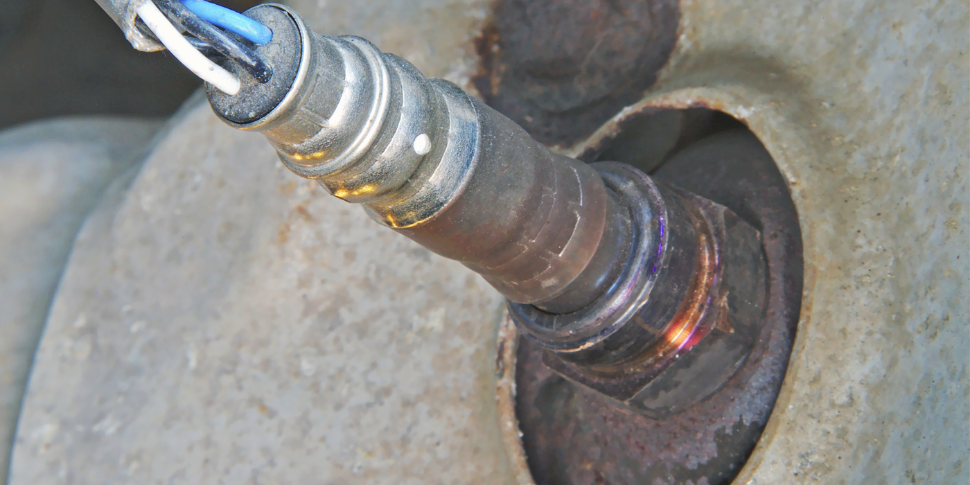
To simplify the concept for 1996 and newer OBDII vehicles, let’s begin with the narrow-range zirconia-ceramic (ZrO) oxygen sensor (also called a “Lambda” sensor), which is designed to monitor mid-range oxygen levels in the exhaust gas stream.
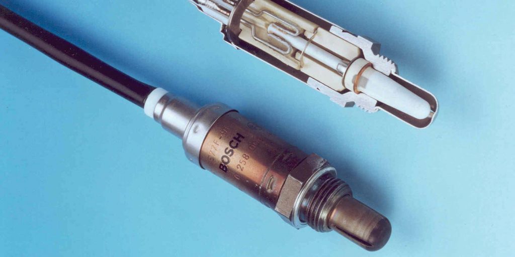
The single-wire zirconia/ceramic “thimble” is contained in a stainless-steel shell. One side of the zirconia thimble is exposed to exhaust gases while the other side is exposed to atmospheric oxygen, which is actually delivered to the thimble through the sensor wire itself. To ensure absolute accuracy, the negative side of the sensor thimble is normally grounded inside the ECM.
Above idle speed, the zirconia thimble becomes electrically active as it approaches 725 degrees F operating temperature. Because the narrow-range zirconia sensor can’t pin-point stoichiometric, the ECM cycles approximately between 0.8 volts (rich) and 0.2 volts (lean). Stoichiometric or Lambda is indicated only when the switching process passes “center” at .450 volts. This switching pattern can be easily observed when using a lab scope or a scan tool equipped with a voltage graphing feature (see photo 1 below).
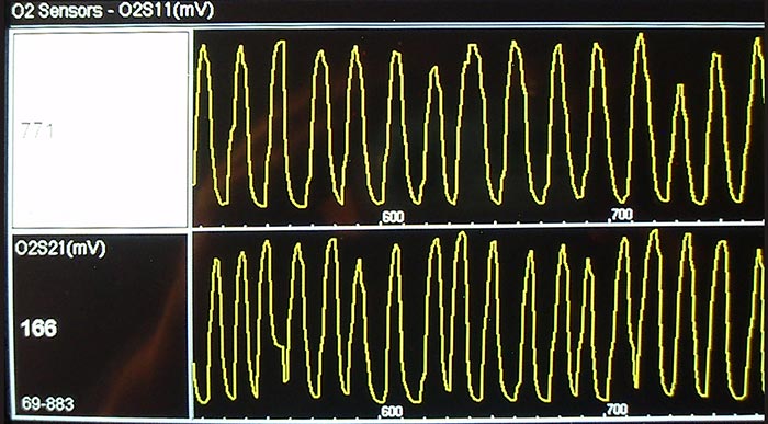
Photo 1: This narrow-range O2 sensor is switching from about 166 mV to about 883 mV, which is slightly out-of-range, but not far enough to store a DTC.
Since 1996, narrow-range zirconia sensors are most often used downstream of the catalytic converter to monitor catalytic converter performance. In brief, the downstream zirconia sensor voltage hovers around 0.7 volts, indicating to the ECM that the catalytic converter is performing to specification. In addition, downstream sensors can provide a default value when an upstream sensor fails. Depending upon application, the down-stream zirconia sensor can affect fuel trims as well.
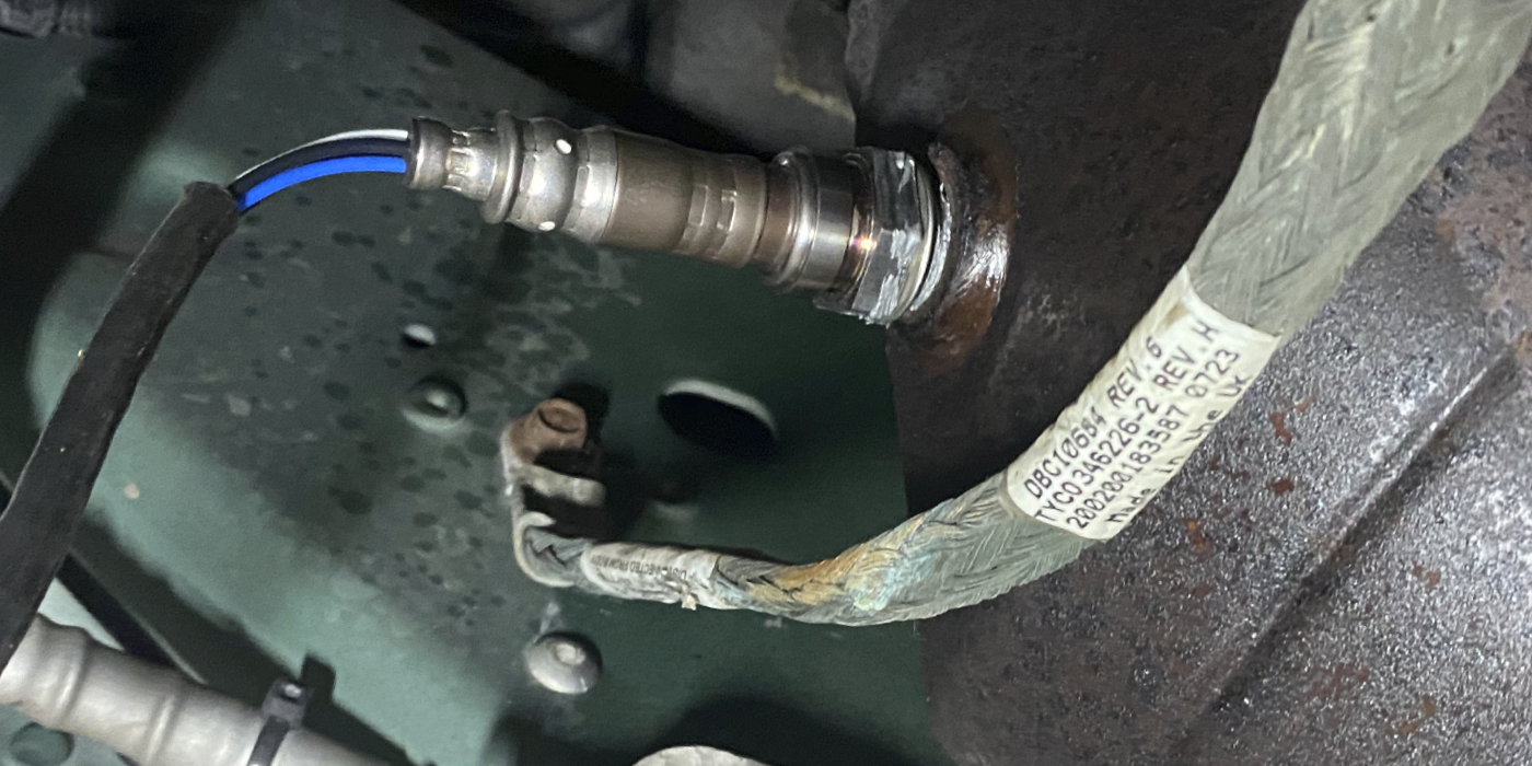
AIR/FUEL RATIO SENSORS
While space doesn’t allow a detailed explanation of how AFR sensors work, let’s summarize by saying that the AFR is basically composed of two zirconia-based thimbles that achieve electrical balance by using a small amperage flow from the ECM to indicate exhaust oxygen. The amperage flows through the AFR sensor and returns as signal data to the ECM. The amperage flow from the AFR sensor is linear or “straight-line” as opposed to the switching effects for a narrow-range zirconia sensor.
Due to their extreme accuracy and broader range, AFR sensors are used upstream of the catalytic converter and, since we’re adding a current flow through the sensor circuit, AFR sensors generally use five or more wires to monitor exhaust stream oxygen.
Be aware that different scan tools might display AFR data on a zirconia-type 0.0 to 1.0-volt scale. Other scan tools might display the actual return signal amperage or voltage according to application. Others might display AFR as Lambda. Lambda 1.0 = center, while .8 Lambda = rich and 1.2 Lambda = lean.
Using Toyota as an example of how most manufacturers display AFR data, the direction of amperage flow in the return signal indicates the air/fuel ratio. A negative current flow indicates a rich mixture while a positive current flow indicates a lean mixture. A zero current flow indicates stoichiometric or Lambda, which is translated into 3.3 volts or “center” on the scan tool. Greater than 3.3 volts = lean while less than 3.3 volts = rich on Toyotas.
STOICHIOMETRIC
Stoichiometric occurs when the ECM achieves a 14.7:1 air/fuel ratio by weight, which produces an .450-volt input from narrow-range zirconia sensor. A voltage less than .450 indicates insufficient fuel (lean), while more than .450 indicates excess fuel (rich). 3) Also called “Lambda,” a stoichiometric 14.7:1 air/fuel ratio completely consumes all available oxygen and gasoline contained within the engine’s cylinders during combustion, which increases fuel economy and reduces exhaust emissions.
OPEN/CLOSED LOOP
“Closed loop,” is established on 1996 and later OBD II vehicles as soon as the ECM receives a voltage signal from the oxygen sensors. ECM. To reduce response time for entering closed-loop operation, ECM-controlled sensor heaters are built into the sensor body. Oxygen sensor heaters use one B+ and one B- ground wire with the ground circuit usually being controlled by the ECM. Sensor heater operation is critical because narrow-range sensors must reach at least 725 degrees F and AFR sensors must reach at least 1,200 degrees F before they become electrically active.
In some applications, a DTC will be set if the oxygen sensor fails to warm up in a specified time. Cold-weather driving can lengthen the warm-up times on some aftermarket downstream replacement sensors and subsequently set applicable codes.
Sensor heaters can be powered through relays, fuses, fusible links and even through the ECM itself. In most cases, the heater circuit fails inside the sensor. In other cases, a heater wiring harness can short to ground or go open-circuit.
SCAN TOOL DIAGNOSTICS
Looking at OBD II DTC definitions, we might literally see dozens of DTCs related to AFR and narrow-range oxygen sensor performance. In brief, sensor monitors can measure data like heater warm-up times, switching frequencies and voltage amplitudes for each AFR and narrow-range zirconia sensor. A diagnostic trouble code illuminates the CE warning light whenever an individual sensor fails its diagnostic monitor (see photo 2)
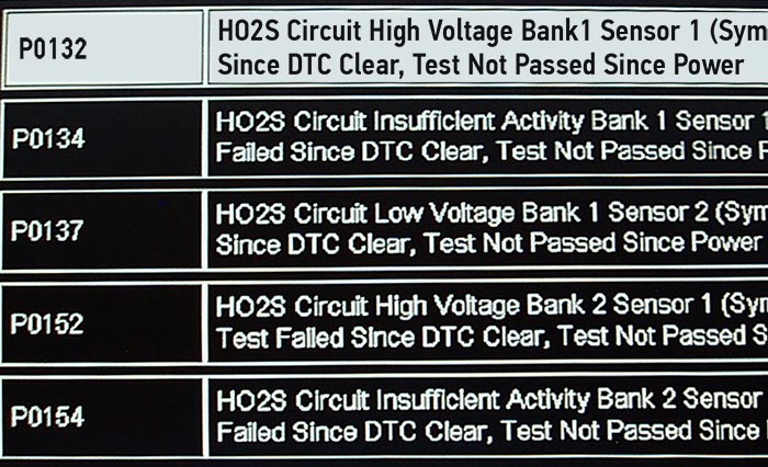
Photo 2: Notice that the DTCs in this screen capture are showing erratic rich/lean fuel control. See the “Applied Diagnostics” Case Study for explanation.
The exact code number, enable criteria, and freeze-frame data are essential for accurately determining why we’re seeing an AFR sensor DTC. I fully recommend capturing all sensor codes on your scan tool or jotting them on a note pad because once erased, a specific DTC might be difficult to duplicate, even during multiple test drives.
APPLIED DIAGNOSTICS – CASE STUDY
2014 GMC K2500 Intermittent Loss of Power Complaint
Stepping from theory into the real world, let’s look at a 2013 GMC K2500 pickup with 144,000 miles on the odometer and an intermittent low power complaint.
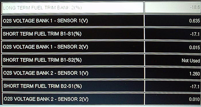
Note that bank #2 voltage is very high (1.26 volts) while bank #2 fuel trims are very negative, -17.1% (see sidebar). DTC P0132 (B1 high voltage) was stored in the PCM.
1) Due to an apparent misfire condition, the intake gaskets, spark plugs, wires, catalytic converter and all four narrow-range oxygen sensors had been replaced.
2) Looking at the O2 sensor data, short-term fuel trims (SFTs) are -17% for both banks.
3)Oxygen sensor voltages for the B1S1 upstream sensor is 0.635, which is close to stoichiometric. B2S1 sensor voltage is excessively high at 1.260 volts.
4) The SFTs indicate that both banks are intermittently generating 1.260 volts, which is causing the ECM to drastically reduce fuel injector pulse width, which in turn is causing the loss of power.
5)In one road test, the SFTs were at a fixed -29% and 1.26 volts when the engine lost power.
6) The fixed number of -29% and 12.6 volts on both banks indicated that the ECM might be causing the low power complaint.
7) Relearning the fuel trim would restore normal operation for 2-3 days, then the SFTs would reset to -29% and O2 voltages would “stick” at 1.26 volts.
8) Like many vacation drivability disasters, the truck owner had run out of money at that point, but I had collected enough data to speculate on the cause.
9) According to freeze frame data, the -29% LFT and 1.25-volt sensor signals were exact numbers that appeared concurrently with the loss of power.
10) From past experience, exact numbers usually indicate a problem with the ECM.
11)I’m speculating that the unswitched 1.25-volt signals from both upstream oxygen sensors could likely be caused by a high resistance in the ECM’s internal or external ground circuits.
12) Using a professional multimeter to test both oxygen sensor ground circuits for key-on voltage should have confirmed or denied my diagnostic hypothesis.