 The Ford Escape is one of the longest running Ford platforms with models that remained unchanged mechanically from 2000 to 2010. While it is not the most complicated alignment, it does have some quirks that have emerged during its past 10 years of service.
Front Suspension
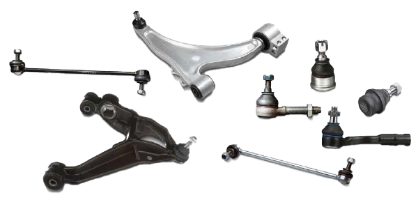
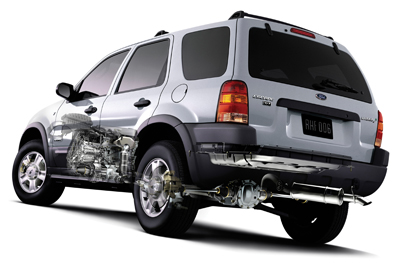 The front suspension of the Escape is a conventional strut design. The lower control arm and cradle is where it gets interesting. The lower control arms use a bushing setup that requires careful inspection. According to Ford, light cracking on the outer surfaces of the rear bushing is normal.
Cracks can go as deep as 10mm (3/8”) without affecting bushing function. Bushings with a separation or crack greater than 3/8″ (10 mm) in depth should be replaced. 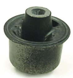 The customer may hear a bang or clunk in the front suspension if there is enough separation for the arm to contact the subframe.
Many a technician has gone looking for a clunk in the front end only to find out it is not the lower control arms, but the front sub-frame mounts.
Worn control arm bushings will make noise on braking, acceleration and over bumps (especially at low speeds). Front subframe mounts will typically make noise during acceleration and braking. The cause for this noise can be worn bushings, but more than likely the subframe has shifted and the locating pins are making contact with the body.
Ford recommends loosening the subframe bolts and aligning the pins so they do not make contact with the body.
Stock sway bar links are also problematic on the Escape. 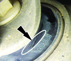 The ball and socket joints on the units can wear and cause a knocking noise over bumps.
Rear Suspension
The rear three-link suspension is the same on both 2WD and AWD models and can stand up to some abuse. The rear subframe can shift over time and cause the locating pins to make contact with the body. They may cause a groan or creak to come from the rear suspension at low speeds. The cure is to loosen the bolts holding the subframe to the vehicle and reposition the pins.
If any of the rear suspension links are replaced, it is recommended that the bolts holding the links are torqued while the vehicle is resting on its wheels.
Front Camber and Caster
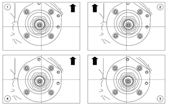 Ford has a limited amount of adjustment built into the upper strut mounts. The upper strut mount has three different positions that can change the camber and caster by ±.39º from the baseline.
If just a camber correction is necessary, it is easier to replace the upper strut-to-knuckle mounting bolts with cam bolts. These bolts can change camber by ±1.75º without altering the caster.
Rear Toe and Camber
The toe is adjustable by cam bolts at the 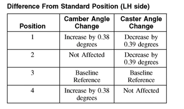 front of the trailing links. Do not remove the rear knuckle cam nut and wheel knuckle bolts. If removed, clean the serrations in the bushing sleeve with a wire brush and install a new wheel knuckle bolt and cam nut. If the area is severely corroded, it might be necessary to clean the area around the plate to ensure proper clamping loads.
If the rear camber is out of specification, there are aftermarket 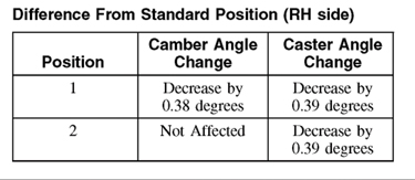 adjustable upper links that can change the camber by ±2º. But, first check ride height before proceeding.
Steering Wheel Position Sensor Calibration
If a toe adjustment or steering component is replaced on 2008 and newer Escapes, the steering position sensor must be calibrated. A scan tool is required.
Hunter’s CodeLink tool which is programmed to address Ford’s requirements relative to the VSC and electric steering reset process. Hunter has simplified the process with a seamless transition from the final front toe adjustment to the required reset of the components associated with the recalibration of the steering position sensor.
Here is the procedure from the Ford’s workshop manual:
1. Place the vehicle on a flat, level surface with the transmission in PARK.
2. Place the steering wheel in the straight-ahead position and remove hands from the wheel.
3. Connect the scan tool to the vehicle.
4. Turn the ignition key to the RUN position.
5. Using the scan tool, select the steering position sensor calibration and follow the scan tool instructions.
6. Clear any power steering control module DTCs.
7. NOTE: After turning the ignition key to the OFF position, wait at least 25 seconds before carrying out any procedures that require the battery to be disconnected or module memory loss may occur.
Turn the ignition key to the OFF position.
8. Road test the vehicle. If the steering wheel is not in the straight ahead position while driving on a flat road surface, check and adjust the alignment as necessary.
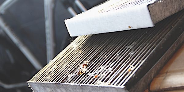
TPMS
TPMS was standard for the 2007 model year and options for 2005 and 2006 Escape Models. 2007-2009 models have banded sensors, while most 2010-2011 models have sensors mounted behind the valve stem.
If the vehicle has been stationary for more than 30 minutes, the sensors will go into a “sleep mode” to conserve battery power. It will be necessary to wake them up so they will transmit the latest tire pressure information to the Smart Junction Box (SJB).
Activation
1. Turn the ignition switch to the ON position.
2. Position the TPMS tool against the LF tire sidewall, accross from the sensor. The TPMS tool must remain in place 180 degrees from the valve stem for 2007-2009 models with banded sensors and directly below the valve stem on the sidewall for 2010-2011 models with the valve stem mounted TPMS sensors.
3. NOTE: The TPMS tool will provide feedback in the form of a flashing green light and a beep for each successful response from a sensor. Press the test button on the TPMS tool to activate the sensor. Activate the sensor at least two times.
4. Repeat Steps 2 and 3 for the remaining tires.
Relearn
1. Turn the ignition switch to the OFF position. Then, press and release the brake pedal.
2. Cycle the ignition switch from the OFF position to the RUN position three times, ending in the RUN position.
3. Press and release the brake pedal.
4. Turn the ignition switch to the OFF position.
5. Turn the ignition switch from the OFF position to the RUN position three times, ending in the RUN position.
The horn will sound once and the indicator will flash if the training mode has been entered successfully. If equipped, the message center will display “TRAIN LF TIRE.”
6. It may take up to six seconds to activate a tire pressure sensor.
Press and release the test button on the TPMS tool. The horn will sound briefly to indicate that the tire pressure sensor has been recognized by the vehicle.
7. Within two minutes of the horn sounding, place the TPMS tool on the correct position for the sensor and release the test button to train the right front tire pressure sensor.
8. Do not wait more than two minutes between training each sensor or the Smart Junction Box (SJB) will time out. Repeat Step 7 for the right rear and then left rear.
The procedure is completed after the last tire has been trained. When the training procedure is complete, the message center (if equipped) will display “TIRE TRAINING COMPLETE.”
For vehicles not equipped with a message center, successful completion of the training procedure will be verified by turning the ignition switch to the OFF position without the horn sounding. If the horn sounds twice when the switch is turned to the OFF position, the training procedure was not successful.