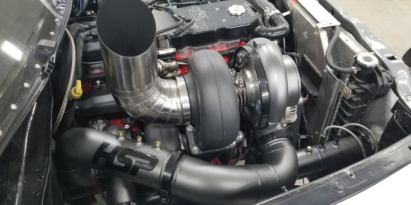
Some ride height sensor modules connect to the Controller Area Network (CAN) bus or other SAE or ISO bus or ride control module. The module can connect directly to the ABS/ESC module on a CAN bus or it can be part of the overall CAN Network in a loop that connects various modules in the vehicle.
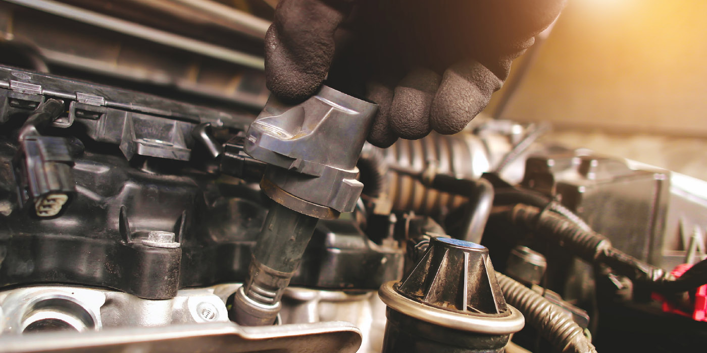
One way to test modules and ride height sensors on a high-speed CAN bus is with a scan tool. Most tools are able to look at the data directly. But, some scan tools may not be able to look at the datastream directly for a ride height sensor signal due to software issues with the tool.
If you are in this situation, it is possible to observe how the actuation of a sensor, switch or component activation can change activity on the data bus. All CAN bus modules have power and two high-speed CAN wires.
If you connect your scope between chassis ground and the bus wires in the OBDII DLC and look at voltage, it is possible to see packets of data being communicated on the bus as the sensor or vehicle height is changed.
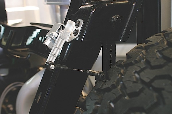
On a direct-type ride height CAN sensor, you can see the sensors communicating with ABS/ESC module as the sensor arm or vehicle is moved. It is impossible to tell what is being communicated, but it is possible to see they are communicating.
This module is not a box, but part of the column. This module might have multiple can lines coming out of it.