A customer calls and tells you his car has suddenly went from highway speeds to idle. The check engine light is on, and no matter what he does, the car won’t go above 30 MPH. What’s wrong? Without looking at it we can only speculate, but I’ll bet it’s going to lead to a problem with the electronic actuated throttle system.
What’s a TAC?
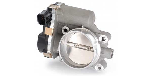
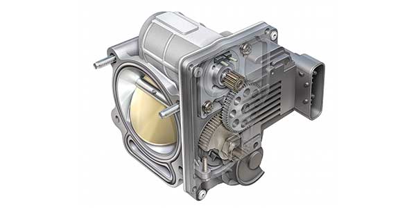
A TAC (Throttle Actuator Control) or ETC (Electronic Throttle Control) system consists of three major components: an accelerator pedal module (with two or more independent throttle position sensors), a throttle valve (throttle plate) that can be opened and closed by an electric motor, and a control module (PCM). The throttle housing or TAC will have its throttle position sensors as well. These TP sensors work together to double check the actual position of the throttle plate and keep the PCM informed of its actual position.
The benefits of electronic throttle control go largely unnoticed by most drivers because the aim is to make the vehicle’s electronic powertrain control virtually invisible to them. The electronic throttle control is also working ‘behind the scenes’ to dramatically improve gear changes and deal with any dramatic torque changes associated with rapid accelerations and decelerations. The system is also working with the traction control, crash avoidance systems and braking systems. Another feature is the BTO (Brake/Throttle Override). The PCM looks at the brake input signal and throttle angle, and if the PCM determines that you have your foot on the brake at the same time as the gas, the brake override system will activate.
Nowadays, the vast majority of drivers have no idea how much intervention the computer has in their daily driving. They only notice something is wrong when the service light comes on, or the vehicle suddenly goes into limp mode. That’s where the technician takes over.
Diagnostic Example: 2010 Chevrolet Express Van – 4.3L
Step 1 – Verify customer complaint
I know this is time-consuming, but it’s the way every diagnostic procedure should start and end. Verify, repair and then verify the repair.
Step 2 – Get the code
Only one code was stored — P2135 TP 1-2 correlation. The TP sensor on this vehicle is a Hall Effect type. The PCM provides a 5-volt reference voltage to the sensor circuit in the TAC module. TP sensor 1 determines the actual throttle valve position, while TP 2 has a voltage reading twice that of TP 1 at idle. TP 2 is a backup value for TP 1.
So what causes the code?
Primarily, it’s the PCM watching the voltage readings of the TP sensors. If the PCM sees less than 0.02V difference between TP 1 and TP 2 for more than two seconds, it will set the code (service light on) and produce the message on the driver’s information screen “Reduced Engine Performance.”
How to verify the problem
Using your scan tool, verify TP 1 parameter (PID) is between 7 – 19%. Check to see if TP 2 has a voltage reading between 2.3V and 2.6V. Observe both PIDs while depressing throttle from closed to full (engine off). Both parameters should change.
Another method is to clear the code, then rapidly move the throttle from closed to WOT and back. This may take several attempts at moving the throttle to see the code a second time.
On this example, TP1 showed 0% angle while TP2 showed 25% angle at idle. Both the accelerator pedal sensors (APP) show 0% angle at idle as well. No brainer at this point.
There are several individual circuit tests that can be performed if you’re unsure at this point. These include testing at the TAC module connector for the TP 1 and TP 2, 5V reference voltage and if there are less than 10 ohms of resistance at terminal 3 and ground. But, the scanner has answered the question for you already. If one of the PIDs did not change as described, or at some point one of them skips over a percentage value as you increase the throttle angle, you’ve found the problem.
Step 3 – Make the repair
Replacing the TAC is pretty straightforward on this model. No need to reset idle or closed throttle position. However, on a lot of imports and a few domestics, you’ll need to read up on the procedures to take care of that issue.
Step 4 – Verify Repair
The best method to verify the repair is to hook the scanner back up and observe the PIDs. Follow the same procedures as before — moving the throttle from closed to WOT while observing the action of TP1 and TP2. The values should correspond to your repair manual information.
On this vehicle, there are eight related service codes for the TAC. Each has its own specific testing procedures that need to be followed. They’re not hard. It’s just another testing procedure that the modern tech will be seeing a lot of in the future. Get a good quality scanner, learn to read those PIDs and you’ll have your customer’s vehicle back on the road in no time at all.