 Models:
2006-’07 Buick Rainier, Chevrolet Monte Carlo
2006-’08 Pontiac Grand Prix
2006-’09 Chevrolet Impala SS, TrailBlazer, GMC Envoy, Saab 9-7X
2006-’12 Cadillac Escalade; Chevrolet Avalanche, Express, Silverado, Tahoe; GMC Savana, Sierra, Yukon
2009 Buick LaCrosse Super, Allure Super (Canada Only) Equipped with V8 Engine RPO LC9, LH6, LH8, LH9, L76, LS2, LS4, LFA, LZ1, L92, L94, L9H or L20, L96, LMF, LMG, LY2, LY5, LY6
 Attention: To properly correct this condition, you must follow both of the procedures to relocate the engine coolant temperature (ECT) sensor and the engine coolant heater cord.
Condition
Some customers may comment that the malfunction indicator lamp (MIL) illuminates after starting the vehicle when they were using the engine coolant heater in very cold ambient temperatures. This usually occurs in a range of -10° to -40° F (-23° to -40° C) or colder.
The technician may observe a DTC P0116 and/or P1400 set as Current or in History.
Cause
This condition may be caused by the engine control module (ECM) determining that the ignition off time requirement has been met at start-up and interpreting the temperature difference between the ECT sensor and the intake air temperature (IAT) sensor as being outside of a calibrated range.
Correction
Important: Do not replace the ECM for this condition.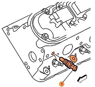
Relocating the ECT Sensor
1. Turn on the ignition with the engine off.
2. Perform the diagnostic system check – vehicle.
– If DTC P0116 and/or P1400 are set and the customer was using the engine coolant heater, proceed to Step 3.
– If DTC P0116 and/or P1400 are set and the customer was not using the engine coolant heater, refer to the DTC list – vehicle in SI.
3. Turn off the ignition.
Warning: To avoid being burned, do not remove the radiator cap or surge tank cap while the engine is hot.
The cooling system will release scalding fluid and steam under pressure if the radiator cap or the surge tank cap is removed while the engine and radiator are still hot.
4. Remove the surge tank fill cap from the surge tank or the coolant pressure cap from the radiator.
 5. Raise and support the vehicle.
6. Place a clean drain pan under the radiator drain cock or under the lower radiator hose, depending on the vehicle.
7. Loosen the radiator drain cock, if equipped, or use J 38185 clamp pliers and reposition the clamp on the lower radiator hose at the radiator.
8. Remove the end of the lower radiator hose from the radiator.
9. Drain the engine coolant sufficiently below the level of the ECT sensor.
10. Close the radiator drain cock or connect the lower radiator hose at the radiator.
 11. Use the clamp pliers to place the clamp into the original position on the hose.
12. Lower the vehicle.
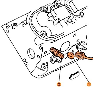
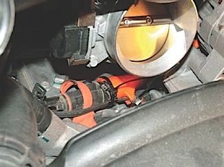
13. Disconnect the wiring harness connector from the ECT sensor (see arrow 2 in Figure 1).
14. Remove the ECT sensor (see arrow 1 in Figure 2) from the front of the cylinder head.
15. Remove the corresponding size plug at the rear of the other cylinder head.
16. Coat the threads of the ECT sensor with sealer. Use GM P/N 12346004 or an equivalent.
17. Install the ECT sensor in the hole of the cylinder head where the plug was removed.
Tighten to 20 Nm (15 lb.-ft.).
18. Coat the threads of the plug with sealer. Use GM P/N 12346004 or an equivalent.
19. Install the plug in the hole of the cylinder head where the ECT sensor was removed.
Tighten to 20 Nm (15 lb.-ft.).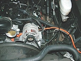
Important: Leave enough wire attached to the ECT sensor harness connector in order to create manageable splices that are at least 1.5” (40 mm) away from the other splice.
20. Extract a portion of the ECT sensor harness wiring and connector from the protective conduit. Cut off the ECT sensor harness connector and wiring.
21. Determine a routing path for the ECT sensor jumper harness wires so that they can be secured to or within an existing protective conduit.
Note: This step is to set up and verify the length of wiring that is required before cutting.
22. Route the ECT sensor jumper wires and then enclose them in their own protective conduit in order to verify the length that is required.
23. Cut the ECT sensor jumper wires to the appropriate length. Note: Adjust splice locations so that each splice is at least 1.5” (40 mm) away from the other splice or connector.
24. Splice the ECT sensor jumper wires to the original ECT harness location using DuraSeal weatherproof splices.
Note: Adjust splice locations so that each splice is at least 1.5” (40 mm) away from the other splice or connector.
25. Splice the ECT sensor jumper wires to the ECT sensor harness connector using DuraSeal weatherproof splices.
26. Connect the ECT sensor harness connector to the ECT sensor.
27. Secure the ECT sensor jumper wires that are in their own protective conduit to or within the existing harness conduit using tie straps.
Important: You must run the engine at the specified rpm and until it reaches normal operating temperature and then allow it to idle as indicated in SI. The engine must then be allowed to cool down in order to top off the coolant level as needed.
28. Fill the cooling system to the proper level.
29. Pressure-test the cooling system.
30. Use a scan tool to clear any DTCs.
Relocating the Engine Coolant Heater Cord
Important: For reference, the procedure and graphics that are shown are from a Chevrolet Silverado, but are similar for the other vehicles listed above.
1. Turn off the ignition.
2. Ask the customer where they would prefer the extension cord to exit from the engine compartment in order to determine the required extension cord length.
3. Obtain an extension cord with the following features: 120 volt, 14/3 gauge, 15A capacity; three prong; polarized plug and receptacle; chemical resistant; grounded terminals; designed for use in a cold outdoor environment; outer jacket resistant to deterioration from moisture, abrasion and exposure to sunlight; and maximum length of 8-10’ (2.5-3 m).
4. Release enough of the clips that retain the engine coolant heater cord to the vehicle to provide the necessary length for repositioning.
5. Apply dielectric grease to the electrical contacts of the heater cord receptacle and the extension cord plug to prevent corrosion. Use GM P/N 12345579 or an equivalent.
6. Connect the heater cord receptacle to the extension cord plug and wipe off any excess grease.
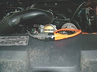
7. Wrap electrical tape around the connection as shown in Figure 3.
8. Route the engine coolant heater cord and extension cord behind the alternator and adjacent to the engine coolant crossover pipe as shown in Figure 4.
9. Continue to route the extension cord to the exit location desired by the customer as shown in Figure 5.
0. Review the routing of the coolant heater cord and extension cord to verify that it does not touch any sharp edges that could damage it.
11. Secure the engine coolant heater cord and the extension cord with tie straps as needed.
12. Resecure any of the original clips that retained the engine coolant heater cord to the vehicle that were released to provide length.
Courtesy of ALLDATA.