If you are diagnosing a “cranks but does not run” or a “lean/stumbling under load” complaint, your first instinct might be a problem with the fuel pump. But, how do you assess the condition of the fuel pump without taking it apart?
Checking fuel pressure is a start for a diagnosis, but it just measures pressure and not the internal condition of the electric motor and the electrical circuit, which provides voltage to the pump. But testing the circuit at the pump might require removing interior components or probing the space between the floor pan and tank.
Current testing of the fuel pump using a scope can give you insights into the inner workings of the fuel pump and the circuit that powers it with zero or very little disassembly.
Tools Required
To measure current, you need a current or amp clamp. The clamp should be in the range of 0-60 amps. It is rare for a fuel pump to pull more than 25 amps. You will also need the appropriate breakout connector to clamp around the circuit either at the fuel pump fuse, power side or relay.
Scope Connections
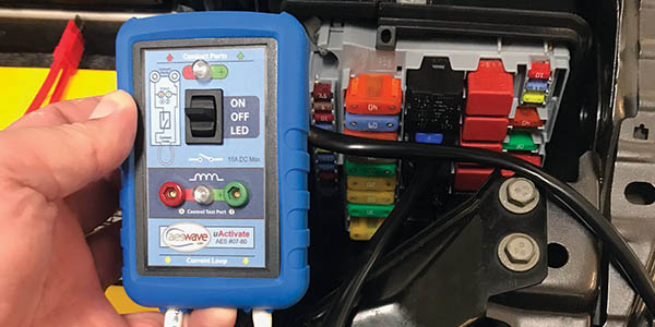
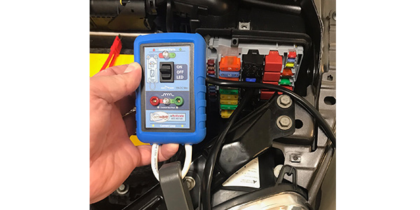
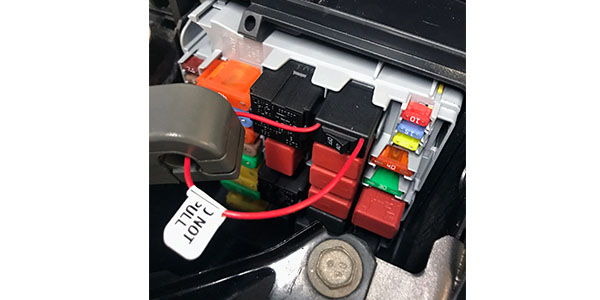
You want to install the shunt/loop/jumper in the fuse box at the fuse or use an adapter. If you are dealing with a vehicle with a fuel module, you might have to clamp around the wire going to the fuel pump. If you are dealing with a situation where the fuel pump circuit needs various criteria to energize, like oil pressure or other inputs from a module, there are tools that can plug into the relay connection and apply power to the fuel pump.
The current clamp can go anywhere on the circuit because the circuit is a loop.
Scope Setup
Set up the correct scale for the clamp you are using. Some scopes have built-in probe scales for specific current clamps. You should have a 10-amp scale on the scope. The time should be set to 2 ms per division to get enough of a parade of the waveform on the screen. Triggers are not required.
What is on the waveform?
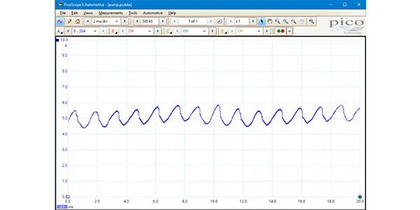
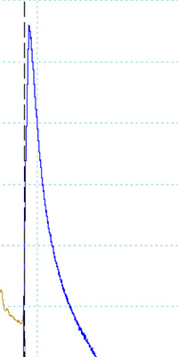
On the scope, what you are seeing is the number of amps the fuel pump is pulling from the electrical system. It is normal to see the pump pull the greatest number of amps when it is first energized.
The cyclical wave you are seeing is the armature of the fuel pump and how the wrapped coils, or the armature or field coils, and the permanent magnets in the case are acting against each other as DC voltage is applied. Each hump is power flowing from the positive and negative brushes that are 180 degrees apart through the commentators and into the windings on the armature. Most fuel pumps have between four to eight sets of commutators.
If there is a problem with a commutator, like a failed solder joint or worn surfaces, the current requirements change and so does the waveform.
Good or Bad?
If you increase the time base or scroll through the saved frames to get a few seconds of runtime on the waveform, you can see the full event. The fuel pump start should be the period when the pump consumes the most current/amp. For a few milliseconds, the line should be a downward slope. This spike is there because the current is required to get the motor and pump turning. If it stays high, there might be a problem with the circuit and high resistance or a problem with the brushes. As a rule of thumb, the initial current draw should not exceed the rating of the fuse.
After the downward slope, the fuel pump should be a uniform wave up and down. If there is an abnormal spike, you might notice it repeats. This is the suspect commutator pair passing by the brushes. From this, you can count the number of commutators on the motor. If the pattern is erratic, it could be a sign the bearings on the shaft of the motor are worn out. If you notice the waveform looks flat with very wide peaks, it could be a sign the brushes are worn out.
The amount of current that is drawn by the pump is dependent on the demands of the engine and possible restrictions in the system. It is tough to come up with a universal number due to the number of fuel pumps and vehicle designs. Very few manufacturers will publish the specification in their service information. But, some scope manufacturers, service information providers and technician communities can provide make and model specific “known good” waveforms.
A lot of late-model vehicles have a fuel pressure sensor at the fuel rail. This data PID for fuel pressure can be critical in a diagnosis of a fuel pump. It can also save you from hauling out the fuel pressure gauge and the assorted fitting to make a connection. Also, some vehicles have eliminated the test port on the fuel rail. But, how do you know the fuel pressure sensor is bad?
If you doubt the numbers from the fuel pressure sensor, you can attach the fuel pressure sensor. But, in some cases, it might be more prudent and easier to check the health of the circuit. Just about every fuel pressure sensor has three wires for power, ground and signal. The diaphragm in the pressure sensor changes resistance as the pressure changes. If there is a problem with the power or ground, and less than the reference voltage is delivered, the sensor will read lower than expected.