General Motors launched the Duramax Diesel 6.6L V8 engine in the Chevrolet Silverado and GMC Sierra 2500HD and 3500 Series trucks with Allison automatic transmissions in 2001. The application expanded to the Chevrolet Kodiak and GMC Topkick medium-duty trucks for 2003, with 16,000-, 18,000- and 19,500-lb. gross vehicle weight ratings (GVWR).
According to its engineers, the Duramax Diesel 6.6L V8 features two key characteristics: incredible torque to tow or haul loads, and higher-rev horsepower for smooth, flexible over-highway travel.
Turbo Improvements
Refinements in 2005 included an overall reduction in exhaust emissions and an increase in torque output, which was enabled by significant hardware changes in 2004. Those changes included a new variable-geometry turbocharger. Self-adjusting turbine vanes and sophisticated electronic controls automatically adjust boost pressure and exhaust backpressure. The vanes direct exhaust gas at the turbocharger’s turbine blades. These vanes can be opened or closed to vary the amount of boost pressure. An electro-hydraulic device operated with engine oil, similar in concept to a camshaft phaser, adjusts the turbine vane angle. The variable-geometry turbo has its own sensors managed by the engine control module (ECM). A solenoid controls oil pressure against a piston that operates a small cam, which works on a unison ring that moves the turbine vanes simultaneously. As the cam turns, it varies the angle of the blades relative to the turbine wheel. The crucial advantage: With the moveable blades, boost pressure can be controlled independent of engine speed. The variable-geometry turbo presents a number of benefits over the conventional fixed-geometry type. Boost can be controlled more precisely, with a greater range of modulation, than with a fixed-blade turbine. The Duramax 6.6L’s turbo eliminates the need for a wastegate, which is often the first turbocharger component to fail as mileage accumulates. Because the variable-geometry turbo can essentially change resistance and adjust the amount of exhaust backpressure, it also eliminates a separate exhaust pressure regulator, which was previously used to manage engine or compression braking.
Maximum boost in the Duramax 6.6L remains 20 psi. Yet boost pressure can be varied more subtly over the engine’s rpm range. This presents itself to the customer as more immediate engine response, with virtually no turbo “lag.” Equally important, the ECM measures a number of parameters, from operating temperature to engine speed to fuel injection timing to load demands, when managing the turbine vanes and controlling boost, so the turbocharger operates more efficiently in all conditions.
2006 Improvements
Late in the 2006 model year, structural changes to the block and connecting rods increased the strength of the engine, which allowed calibration changes that increased output for the applications in the Chevrolet Silverado and GMC Sierra pickups.
For the 2006 model year, a new fuel pump increased fuel pressure from 23,000 psi (roughly 300 times greater pressure than the typical gasoline injection system) to 26,000 psi, and the fuel lines and rails have been strengthened for the higher pressure. Also in 2006, the compression ratio was lowered from 17.5:1 to 16.8:1 to improve the operating smoothness of the engine.
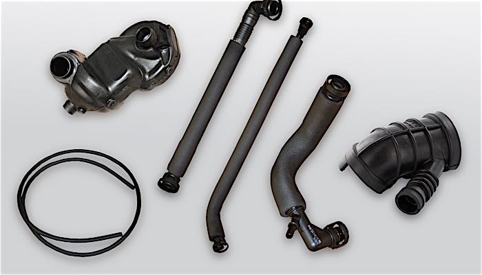
As continuing development aimed at lowering diesel emissions progressed, the exhaust gas recirculation (EGR) system was enlarged for the 2006 model year and installed in all Duramax 6.6Ls. The EGR system recycles some exhaust gas back into the intake stream to cool combustion and reduce oxides of nitrogen (NOx) emissions. The Duramax Diesel 6.6L V8 system features a unique cooling process that increases its effectiveness. Hardware required includes: plumbing that carries some exhaust gas from the turbocharger to the intake, an EGR control valve and a stainless steel cooling element. The EGR valve is managed by the E35 ECM.
The EGR cooling element bolts to the right side of the engine, on the inboard side of the cylinder head, with jackets fed by engine coolant. Returned exhaust gas passes through a spiraled passage in the element, and the temperature of the gas is lowered before it returns to the combustion chamber.
Latest Engine Designs
For 2007, the latest version of the Duramax 6.6L is equipped with two-piece rocker covers that accommodate external connections for the fuel lines and new fuel injectors. These resemble conventional rocker covers, but they are split lengthwise along the plane of the top surface of the cylinder head. The lower, rectangular piece of the rocker cover rings the perimeter of the cylinder head and bolts to the head like a conventional cover. The upper portion of the rocker cover attaches to the lower piece. The new two-piece rocker covers ease access to the fuel rails and injectors. Previously, the rocker covers and then the fuel lines had to be removed in order to reach the fuel injectors. The top piece of the new rocker cover is scalloped on its lower edge, around the point where the injectors fit into the cylinder heads. The injectors are now exposed on the engine, and can be removed with no other disassembly required. Such serviceability considerations are particularly significant in an engine like the Duramax 6.6L, with an anticipated useful life beyond 200,000 miles.
Fast-heating glow plugs reduce pre-start heating time without increasing draw on the battery. The engine’s glow plugs draw 6.6 watts of electricity, as before, but the element has been redesigned to more efficiently convert electricity to heat. Moreover, the glow-plug controller is specifically calibrated for the Duramax 6.6L’s new engine control module and allows pulse width modulation, which manages current more like a rheostat than an on-off switch.
INTERNAL AFFAIRS
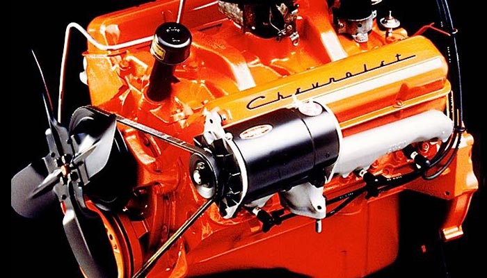
The 90° turbodiesel V8 utilizes a compact, rigid cast-iron engine block that features induction-hardened cylinder bores — a technique borrowed from larger diesel engines and exclusive in the pickup class — and four-bolt, crossed-drilled bearing caps. A die-cast aluminum lower crankcase strengthens the engine block and serves as the lower engine cover, keeping weight down. The forged steel crankshaft is surface-hardened by nitriding, and aluminum pistons minimize reciprocating mass and improve efficiency. Each has a small hole cast in its skirt, allowing jets to spray cooling oil through a cast channel and up toward the bottom of the piston bowl, where most heat is generated.
Aluminum cylinder heads deliver strength greater than or equal to cast iron with considerably less weight. The Duramax also has four valves per cylinder — the standard for contemporary luxury-car diesels — and an integrated oil cooler. Several features make it easier to service, which is good news for technicians. Its compact size leaves more space around the engine when it’s installed in the vehicle. The timing gears are at the front of the engine for easy access, and in heavy-duty pickups, technicians can remove the fuel filter simply by leaning into the engine compartment.
The Duramax 6.6L operates on the direct injection principle which, other things equal, allows more complete combustion than the older style indirect injection and decreases specific fuel consumption as much as 20%. Each high-pressure injector has its own solenoid to manage fuel spray. The latest injectors feature six spray points in each injector tip for better fuel vaporization. The solenoid-type injectors reduce the amount of fuel leakage between pulses. They allow more precise fuel control, with more consistent performance under hot-fuel conditions, and greatly reduce the potential for clogging due to fuel contamination.
The injectors are installed directly into the head and are coded so that the E35 ECM can precisely match the flow characteristics of each injector on a particular engine to compensate for small variations, ensuring exact fuel delivery.
Service Solutions for the 6.6L
Q: The GM 6.6L Duramax has different thickness head gaskets. Which one should I use? A: In 2003, the AERA Technical Committee offered the following information regarding cylinder head gasket selection on 2001-’03 GM 6.6L VIN 1 Duramax diesel engines. Using the wrong head gasket on this engine could cause engine damage. GM offers three different thickness head gaskets depending on the amount of piston protrusion the engine has. When measuring piston protrusion, make sure that you measure all pistons on each bank.
Notice: The left and right cylinder head gaskets are not interchangeable. Improper placement of the cylinder head gasket will block coolant and oil passages and will cause severe engine damage. The gasket markings face up when correctly installed.
In late 2006, the AERA Technical Committee offered additional information regarding a head gasket design change on 2001-’06 GM 6.6L Duramax engines. Special surface cleaning procedures must be followed to allow a proper seal when using the new design head gaskets along with a change in the torque angle specification.
A mid-year design change was made to the head gasket of the 2006 Duramax diesel engine. This second-generation head gasket will service all 2001-’06 vehicles, including those that were built with the first generation head gaskets. The second generation head gasket does require a lower head bolt torque angle specification as well as special cleaning methods of the gasket surface.

The second generation gasket can be visually identified by its riveted construction as opposed to the crimped design of the first generation gasket (see Figure 1).
For vehicles that were equipped with the first generation head gasket, special attention must be given to the cleaning of the engine block and head gasket surfaces when the second generation head gasket is to be used. Over time, the crimped areas of the first generation gasket may allow corrosion buildup where they contact the block and head surface areas.
Inspect the gasket sealing surface for corrosion, especially in the areas that were in contact with the crimped tabs of the first generation head gasket. For surfaces that have corrosion or pitting in them, wrap a piece of flat steel with #600 grit wet grade sandpaper. Use a moisture-displacing lubricant (P/N 1052864) or equivalent to wet sand the block surface to remove any remaining gasket material or corrosion. Do not use any paper coarser than #600 grit.
Take care to keep the sanding block parallel to the block surface and evenly sand the sealing surface. Some areas of corrosion will still show a stain. Do not attempt to wet sand these areas down to a shiny metal surface. Change sandpaper as necessary, and clean surface with brake parts cleaner along with the head bolt holes and cylinder bores.
The second generation head gasket requires a lower torque angle specification for the M12 bolts. The M8 bolt torque remains the same. M12 bolts should be torqued to the following specifications:
1) 37 ft.-lbs.
2) 59 ft.-lbs.
3) 60°
3) 60°
M8 bolts should be torqued to 18 ft.-lbs.
Q: Some engine technicians have reported an oil cooler leak on 2001-’04 GM 6.6L VIN 1 and 2 diesel engines. What could be causing this?
A: Minor imperfections in the engine block’s machine surface at the oil cooler interface may allow engine oil seepage past the oil cooler O-rings. To cure this problem, GM offers the following information:
Inspect for other oil leaks, which may be perceived as an oil cooler leak. An oil leak from one of the main bearing cap side bolts may appear to be coming from the oil cooler.
If the oil cooler is leaking, remove the oil cooler from the engine. Use care to remove only the five bolts that hold the oil cooler to the engine block.
Remove the O-rings from the oil cooler and discard them.

Clean the mating surfaces of the engine block and the oil cooler.
Install new O-rings (2) to the oil cooler
(see Figure 2)
- .
Apply sealant (1) P/N 97720043 to the oil cooler as shown in Figure 2. Do not apply sealant to the O-ring grooves on the oil cooler.
Install the oil cooler to the engine block. Torque the five oil cooler assembly bolts to 18 ft.-lbs.
Allow the vehicle to sit for eight hours at room temperature for the sealant to fully cure before initial startup.
Q: I’ve had some 2001-’04 GM 6.6L diesel VIN 1 engines owners comment on engine coolant loss with no visible leaks. They also complain of extreme white smoking. Is this common? A:Excessive white smoke or a coolant-type odor coming from the exhaust pipe, along with low coolant levels, may indicate coolant entering the combustion chamber.
This condition may be caused by engine coolant entering the cylinder due to a dirty or damaged seal between the fuel injector sleeve and the cylinder head. Not all fuel injector sleeves may be leaking. A proper pressure test of the cylinder head will reveal any leaking fuel injector sleeves. Once the leaking injector sleeves have been found, remove the sleeve from the cylinder head using a fuel injector sleeve remover/ installer tool, P/N J45910.

After the sleeve has been removed, inspect the inside of the fuel injector sleeve for damage to the injector sealing surface. Damage to this portion of the fuel injector sleeve may indicate a loose injector caused by improper installation or a missing copper washer (see Figure 3). A loose injector will allow the fuel injector and the injector sleeve to bounce inside of the cylinder head, resulting in coolant leaking into the cylinder. If damage is found, replace the damaged components
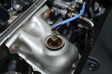
Q: I’ve had a few injector sleeves come out when trying to remove an injector on some Duramax engines. Any tips on how to repair these?
A: The AERA Technical Committee offers the following information regarding injector tube installation for 2001-’06 GM 6.6L Duramax diesel engines. This information should be considered anytime the cylinder heads are being serviced.

This engine uses a removable sleeve to locate and house the injectors for this engine. These sleeves are in direct contact with the engine coolant, which allows the injector to be a constant temperature. On occasion, the sleeve may come out with the injector when it is being removed from the cylinder head. It is important to replace any injector sleeve with scoring or other damage. Clean the fuel injector sleeve lower sealing area and the sleeve bore with GM P/N 12377981 or equivalent. When installing injector sleeves, always use new sealing “O” rings.

Lubricate the new injector “O” rings (1) and place in the injector sleeve (2) grooves as shown in
Figure 4
- .
Apply sealant to the lower sealing area of the injector sleeve.
Place the sleeve in its respective bore and use the sleeve remover/installer tool P/N J45910 to install the sleeve.
Lightly tap on J45910 with a hammer to install and seat the fuel injector sleeve as shown in
Figure 5
- .
Remove J45910 from the fuel injector sleeve.
Install the fuel injector(s).
Sources: GM Powertrain and AERA