By Larry Carley, Technical Editor
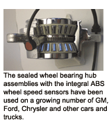
When engineers came up with the idea of putting the wheel speed sensor (WSS) and tone ring inside a sealed wheel bearing hub assembly, it seemed like a great idea. The sealed environment would help protect the sensor and make it less vulnerable to damage or contamination from the outside world. The first of these applications dates back to 1999 on Chevy/GMC and Ford trucks. Since then, the sealed wheel bearing hub assemblies with the integral ABS wheel speed sensors have been used on a growing number of GM, Ford, Chrysler and other cars and trucks.
But there have been some problems. In late 2004 and early 2005, GM in Canada had to recall 1999-2002 model year Chevrolet Silverado, Tahoe, Suburban and Avalanche trucks, GMC Sierra and Yukon, and Cadillac Escalade models because of problems with the wheel speed sensors in the sealed hubs. The same problem forced another recall in 2005 of 1.35 million Chevy and GMC trucks in the U.S. (NHTSA recall 05V379000 dated 8/3/05).
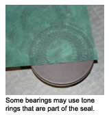
The wheel speed sensor tone ring is built into the wheel bearing assembly, unlike other wheel speed sensor setups where the tone ring is on the outside of the outer CV joint housing, axle or hub. On the later applications, the WSS tone ring is exposed and very vulnerable to corrosion from road salt and road splash. The tone ring can also be damaged if somebody uses a pry bar to separate a halfshaft from the steering knuckle, or drops the halfshaft on the floor. A difference of only a few thousandths of an inch in the height of the teeth on the tone ring can affect the WSS signal.
The signal pulse is generated when a tooth passes under the magnetic tip of the sensor. The tooth passing through the sensor’s magnetic field causes the sensor to act like a little generator and produce an alternating current signal that increases in frequency and amplitude in direct proportion to wheel speed. If you look at the signal on an oscilloscope, it should look like a nice even sine wave with all the up and down humps in the waveform evenly spaced and the same height.
Magnetic sensors can also pickup metallic wear debris from the rotors and pads, causing the sensors to read erratically and confuse the anti-lock brake system. Cleaning the sensors and resetting the air gap can often restore normal operation. But if the tone ring is corroded or damaged, it must be replaced.
 In the case of the sealed hub assemblies with the wheel speed sensor and tone ring inside, the hub provides protection against external corrosion — or at least it is supposed to. But nothing is perfect, and when moisture seeps into the hub it corrodes the tone ring. The result is an uneven WSS signal that confuses the ABS system.
In the case of the Chevy/GMC recalls, road salt was apparently working its way into the hub assembly at the sensor hole and attacking the tone ring. In many instances, the problem was not bad enough to set a fault code and turn on the ABS warning light. But it was bad enough to generate misleading wheel speed readings and trick the ABS system into kicking in and pulsing the brakes when ABS was not needed. The problem typically occurs at speeds under 10 mph, and greater than 4 mph. When the ABS system kicks in, it may increase the stopping distance somewhat compared to normal braking. This has resulted in a number of accidents and injuries (thus the Canadian and NHTSA investigations and subsequent recall notices).
There are a couple of things to keep in mind here. First, though a recall notice was sent out to the owners of the affected vehicles, not all of these vehicles have been fixed. Dealers are supposed to check for applicable recall notices when servicing their customers’ vehicles, but if a vehicle owner never got the notice, forgot about it, ignored it or never went back to the dealer, the potentially troublesome hubs are still on the vehicle.
The fix, in GM’s case, was to pull out the sensor, clean the sensor and tone ring, and dump some zinc anti-corrosion treatment into the hub to prevent further corrosion.
DIAGNOSIS
The first signs of trouble may be the ABS system kicking it when braking at low speed, and/or the ABS warning light coming on. Until you hook up a scan tool and pull the codes, though, there’s no telling why the light is on. The fault may be a bad wheel speed sensor or it might be something else, so don’t jump to conclusions — especially if there are no codes to guide you.
Reading ABS codes requires an ABS code reader, scan tool or scanner software that can access the ABS system. An inexpensive OBD II code reader or an entry-level scan tool designed for a do-it-yourselfer won’t work here. You need a professional tool designed for ABS diagnostics, or a digital storage oscilloscope to look at the wheel speed sensor waveforms.
If the ABS light is on and you find a code for a wheel speed sensor, check the sensor wires for breaks or a loose/corroded connector. Broken wires are probably the leading cause of wheel speed sensor related failures. One some vehicles, the wires tend to be brittle and break as a result of fatigue from road vibration and/or steering maneuvers. Replacing the WSS wiring harness is usually the recommended fix for these situations. You could try to patch the broken wire, but crimp connectors are vulnerable to road splash and corrosion, and solder is usually too rigid and will crack again. Better to replace the wiring harness than to risk a comeback.
If there are no codes, but the vehicle owner complains about the ABS system engaging when braking (noise, vibrations and pedal pulsations), the problem is likely a bad wheel speed sensor. But which one? That’s where a scope can really help you identify which sensor is acting up. Connect the scope to the sensor leads and spin the tire by hand. If you get a good clean signal, move on to the next WSS sensor and so on until you find the one that is generating a bad signal.
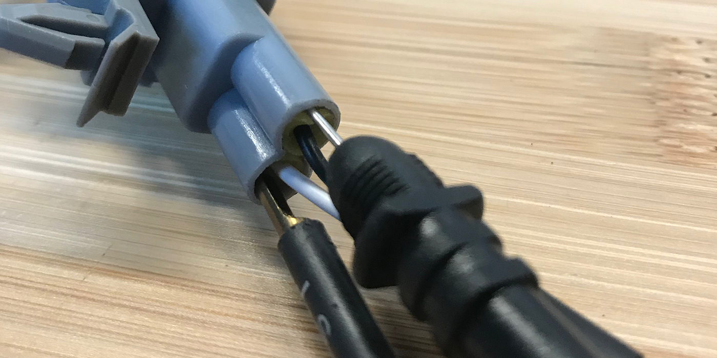
If the scope pattern produced by the sensor is flattened (diminished amplitude) or is erratic, it usually indicates a weak signal caused by an excessively wide air gap between the tip of the sensor and its ring, or a buildup of metallic debris on the end of the sensor. A weak signal can also be caused by internal resistance in the sensor or its wiring circuit, or loose or corroded wiring connectors. You can also measure the wheel speed sensor’s output with a DVOM. The most accurate way to do this is with a breakout box connected to the wiring harness at the ABS module. You can also connect the DVOM test leads directly to the wheel speed sensor itself, but testing the sensor this way won’t tell you if the signal is getting through to the control module. Spin the wheel by hand and note the sensor’s voltage reading.
 A good wheel speed sensor will typically produce an alternating current (AC) voltage reading of 50 to 700 MV when the wheel is turning one revolution per second.
If the voltage reading is low or nonexistent, check the sensor’s resistance (with the key off). This should also be done at the breakout box. Checking resistance of the wheel speed sensor circuit where it plugs into the module will tell you if the sensor’s wiring harness is OK. If you don’t get the specified value (typically 900 to 1,400 ohms), go to the wheel and unplug the sensor from its wiring harness, then measure the sensor’s resistance by attaching the DVOM test probes directly to the sensor leads.
A resistance reading that is now within range tells you the problem is in the wiring, not the sensor. If the sensor itself out of range, high or low, the sensor is defective and the sensor or hub assembly (if the sensor is not removable) needs to be replaced.
 BEARING DIAGNOSIS
Another reason to replace a sealed hub assembly whether it contains a wheel speed sensor or not is bearing wear. If the vehicle owner complains about a slight growl, hum or chirping noise that changes with speed, it may be a bad wheel bearing.
According to a recent Babcox Research survey, 51 percent of bad wheel bearings are identified and replaced as a result of a customer complaining about noise, 24 percent are found during a brake job, and 19 percent are discovered during an alignment.
To check a wheel bearing, grasp the tire at the 12 and 6 o’clock positions and attempt to rock the tire. If you feel any play, the bearings are loose and need to be replaced. Also, rotate the tire by hand. Any roughness or noise from the bearings would also tell you the bearings are worn or damaged and need to be replaced.
You can also measure bearing play by placing a dial indicator against the hub and turning the wheel. Refer to the vehicle manufacturers specifications, but as a rule, no more than .005 inches of play is allowed for most sealed wheel bearing and hub assemblies.
If one wheel bearing is loose or noisy, pay close attention to all of the other hubs on the vehicle, too, especially if the vehicle has a lot of miles on it or has been driven through axle-deep water or been flooded. Chances are some of the other wheel bearings may be going bad, too.
HUB REPLACEMENT
You need to make sure you have diagnosed the fault correctly on vehicles with the sealed hub and ABS wheel speed sensors because the replacement parts are not cheap. The hub and bearing assembly on a Chevy pickup truck, Yukon or Tahoe has a list price of more than $400, and more than $600 on a Suburban! On a Buick Park Avenue, a similar part will set your customer back $323.
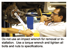
Hub replacement is fairly simple. Remove the wheel, caliper and rotor, then remove the wheel bearing and hub assembly from the spindle or axle. Do not use an impact wrench for removal or installation. Use a torque wrench and tighten all bolts and nuts to specifications.
Many hub units for FWD applications come with a new hub nut. Use it. And be sure to torque it to specifications with a torque wrench — never an impact wrench.
After repairs have been made, you should always confirm the problem has been fixed by clearing any ABS codes and doing a short test drive to make sure the ABS light does not come on and there is no bearing noise.

