This article will document the use of fuel trims and oxygen sensor behavior to determine if the misfire activity is ignition, engine mechanical or fuel related. We will address this in a two-part series from the viewpoint of moments in time to offer a deeper understanding of these concepts.
Our first article on this subject will address ignition-related misfires. We will explore other misfire research in the next article. The first step is to visualize these failures from the beginning 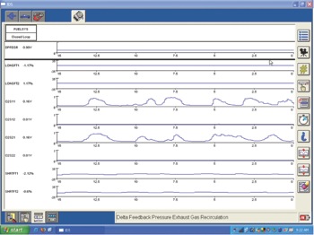
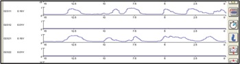 — picture that an ignition-related misfire has occurred on a subject vehicle. We come to define it as a single cylinder misfire, prior to failure the pre-oxygen is switching and working as designed. The post-oxygen sensor is also working as designed and almost appears as a straight line when looked at per graphical data or a Pico lab scope. Figures 1 and 1a denote how the pre- and post-oxygen sensors may look on a subject vehicle prior to any type of misfire-related activity.
Let’s use a 2007 Ford Taurus as an example. The IDS scan tool will be used to show the activity.
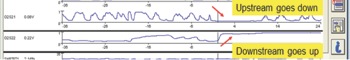
Figures 2 and 2a denote the activity of the pre- and post-oxygen sensors at the initial point of ignition misfire activity. A close examination shows the pre-oxygen sensor went low, indicating that it saw oxygen in the exhaust stream at the very moment the misfire activity occurred. The post-oxygen sensor went high, indicating how the vehicle has a tendency to run (rich).
Note that at the very point of failure, the short-term fuel trim (STFT) will increase and, depending on design and strategy of the system, may show impressive numbers for short term, after the processor has acknowledged this, the resources of long-term fuel trim (LTFT) will work to get the short-term numbers back as close as possible to at or near zero. The end result is that after corrective action has taken place by the processor, there will not be a significant impact on the total fuel trim (ST + LT). This analysis is based on a subject vehicle that has good fuel trim values to start with. A range of +/-5% is optimal on many systems today, but a range of +/-10% may be acceptable.
A great example is a vehicle that has a total correction of 15% prior to fault; you’ll have higher numbers once ignition misfire activity occurs. I’ve found that on many vehicles with ignition misfire activity after the corrective action has taken place, single-digit numbers appear to be reasonable.
2004 Chevy Impala
Now let’s take a look at a 2004 Chevrolet Impala with a P0300 stored in memory.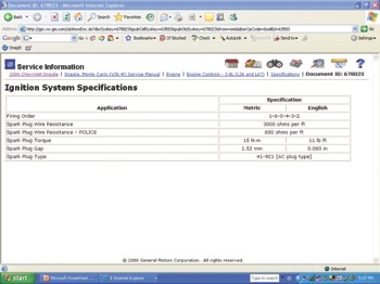
Upon review of this failure, note that the vehicle has a misfire code and freeze-frame information as well. The data shows that a STFT of -4% and a LTFT of 7% was noted; this is a total correction of 3%, which is not a significant impact on the total fuel trim correction. 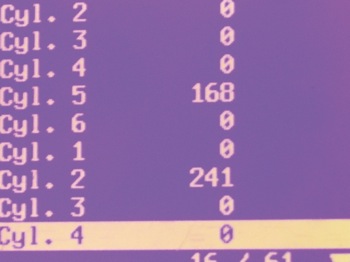
The misfire activity appears to be on cylinders 2 and 5, and, based on service information, it appears that these two cylinders are companion cylinders. See Figures 3 and 4. After careful review of this case study, it was clear that a bad coil assembly was at fault. The Tech 2 scan tool was used for this analysis. This observer would also ask that you take into account systems that will turn off the injectors when misfire activity occurs, the fuel trim values will go to zero once the fault is set.
This Pulling Codes case is now considered closed, however, we invite any questions concerning this fault analysis.