In the year 49 B.C., Julius Caesar crossed the Rubicon River in Northern Italy to become emperor of the Roman Empire. For Caesar, crossing the Rubicon represented the point of no return because it was either going to spell victory for himself or death at the hands of his enemies. Fast-forward to 2012, Chrysler Corporation built a Jeep named the Rubicon, presumably to bless it with the famous river’s sense of adventurous ambiance. Four years later, a red Jeep Rubicon with a black top immersed me in a mysterious and expensive electrical switching system called a Totally Integrated Power Module (TIPM), or (IPM) as it’s occasionally referred to in service literature. Since TIPM failures have caused numerous diagnostic headaches for technicians, I had a unique opportunity to understand how these systems actually work. Working well beyond the point of no return, I discovered a complex system with a unique operating strategy. With that said, let’s depart on what proved to be a difficult and occasionally tortuous diagnostic expedition.
THE HORN HONKS WHEN: This month’s Diagnostic Dilemma begins with a 2012 Jeep Rubicon that honked the horn each time a door was opened. The call came from a small-fleet diesel tech who also gets his share of his business owners’ personal vehicle problems. Doing some information gathering, we discovered that the horn honked when the door was opened or when the exterior or interior lighting was activated. My first instinct was to condemn the mysterious TIPM fuse and relay box assembly. The strange thing was that sometimes the horn wouldn’t honk, which further complicated the diagnosis.
We determined that the right front fender had been replaced and the three grounding studs pressed into the fender had been painted over. We installed ¼” external star washers on the five underhood studs and four interior kick panel studs to insure a perfect ground. Establishing good grounds produced a repeatable failure. We also eliminated the blaring horn noise by substituting the horn with a head lamp that drew about the same amperage.
FAILURE PATTERNS: As mentioned previously, the horn would honk when a door was opened. Going a step further, manually turning on the interior lighting would also activate the horn. Using old-school diagnostics at this point, it would have been easy to assume that the lighting circuit was “shorted” to the horn circuit through the TIPM. To confirm or deny this theory, we removed the TIPM cover and found no burned or cracked areas or evidence of water intrusion on the TIPM’s circuit boards.
A CAN BUS OVERVIEW: Before we get too deep into this case study, let’s cover the pertinent basics of a CAN bus system. CAN bus systems share data among multiple modules by transmitting and receiving digital signals relayed at different communication speeds. This happens along a single or a twisted pair of wires called a data bus. Each module is programmed to recover its own “coded” messages from this shared data bus. The CAN bus might also use a “gateway” module connected to multiple networks to route data to and from different modules at different communication speeds. With CAN, any included switch merely commands modules like the ECM or BCM to perform specific switching functions like cranking the engine or honking the horn. A head lamp switch might, for example, command a module to turn on the exterior lighting. Other modules might command solenoids, motors, and other accessories on or off by activating or deactivating relays. Diagnostically speaking, modern propulsion technology requires high-speed data processing and communications systems. For that reason, CAN bus technology now forms the basic electrical architecture of modern automotive propulsion platforms. Even if you’re attempting to repair something as simple as a taillight or a blower motor, you’re going to need to learn how to diagnose CAN bus systems.
CAN BUS DIAGNOSTICS: Body control diagnostics require good scan tool skills. And, thanks to modern CAN bus communications systems, most professional scan tools now poll all onboard modules to not only indicate the codes stored in each module’s diagnostic memory, but also to ensure that all modules are communicating. In this case, we retrieved a B2339 code from the Cab Compartment Node (CCN) indicating that we had a “stuck” horn switch and a C123C code indicating a random problem within the vehicle’s ABS/vehicle stability control system. Since B2339 was more immediate, we tackled it first. Once cleared, the B2339 code would reset as soon as the ignition was turned on, which made it a “hard” code.
Bidirectional controls are also an essential feature for any modern scan tool. In this case, I could activate the horn using Chrysler’s Actuator Test, which confirmed that the TIPM was functioning as designed. I then consulted wiring schematics to analyze how the electrical and bus communications systems were designed. One horn circuit schematic indicated that the horn switch was a hardwired circuit, which was very misleading. Forging ahead, I discovered that the horn would not honk key-on. Key-off, the horn would honk for exactly 30 seconds, then time out. Another 30 seconds was required before the cycle could be repeated, which indicated that the 30-second cycling event was probably controlled by the TIPM. The horn responded as expected when activated by the key fob.
DIGITAL LOGIC: As all diagnostic techs know, we sometimes have to sleep on a problem to solve it. In this case, it took me another day to process exactly why the TIPM might be activating the horn when interior lighting was commanded on by the door latch sensor. In addition to the TIPM being a fuse/relay box, it also had several circuit boards containing logic chips that obviously were reacting to data inputs. In contrast to the CCN which goes to sleep with the key off, the TIPM remains alert to any command such as the key fob unlocking the doors or the door being opened by the driver.
Holding that thought, the horn provides a mechanical switch command to the speed control switch assembly. The speed control switch contains a “slave” node that converts the horn switch voltage command into a low-speed Local Interconnect Network (LIN) communication signal. The LIN signal is transmitted to the Cab Compartment Node (CCN) located inside the instrument cluster, which acts as a “master” node and essentially functions as a body control module (BCM). The CCN then translates the LIN signal into one of three different CAN signals, which are transmitted to the TIPM. The TIPM then responds to the horn switch command by activating the horn relay, which in turn activates the horn.
If this all sounds like a Rube Goldberg contraption, you’re probably right in the sense that multiple actions and responses must take place to perform a simple act like blowing a horn. On the other hand, if all of the numerous accessories on a modern vehicle were hardwired, very large wiring bundles would be needed to handle switching functions. With the CAN bus, all that’s needed to handle switching functions is a pair of CAN bus wires that transmit commands from a switch to an appropriate module like the CCN.
The real question, of course, is why the horn wouldn’t activate with the key on. Here’s where I get into speculation on what I call operating strategy or “digital logic.” Unlike the TIPM, the CCN isn’t fully “awake” in the key-off mode. The key-off horn switch command is nevertheless transmitted to the CCN, which relays it to the TIPM. The TIPM responds to the horn switch command by activating the horn relay. After 30 seconds of activation, the TIPM’s “digital logic” detects that the horn switch is stuck and disables the horn relay for another 30 seconds before the relay can once again be activated.
All good in theory, at least so far. But why won’t the horn honk in the key-on mode? The answer is relatively simple, but due to a lack of specific service information, this requires some degree of speculation. Nevertheless, with key-on, the CCN is now fully “awake,” which means that the TIPM can now “read” the B2339 code stored in the CCN’s diagnostic memory. As soon as the TIPM detects the B2339 “stuck horn button” code, it disables the horn relay. With that said, we’re going to see much more of this type of “digital logic” or operating strategy built into modules.
WHAT FAILED? Now that I understood how the horn system responded to different inputs, I had to determine which component failed in the horn system. According to various case studies, the most common failures are with the speed control switch and horn switch assembly. According to service information, Jeep revised the wiring harness in the upper steering wheel assembly, presumably because it’s a high-failure item. With the cover removed from the speed control switch, it’s easy to see that the circuit board contains some small, but very important logic chips.
Conventional speed control systems contain a set of resistors that reduce reference voltage into specific voltage levels that command different speed control functions. Not so on the Jeep Rubicon. The speed control switch transmits commands along the LIN bus data line to the CCN located inside the instrument cluster. Just looking at the horn and speed control switch assemblies, I’m speculating that the circuit board had a corrupted component indicating that the horn switch was stuck, when in fact, it tested otherwise. Replacing the horn and speed control switching and wiring assemblies became our Crossing of the Rubicon. Rather than choosing the “silver bullet” repair, I prefer the accuracy achieved by thoroughly researching the problem and applying a logical and meaningful diagnostic procedure.
LESSONS LEARNED: A few days later, I was called to diagnose a right rear wheel speed sensor on a 2008 Jeep Liberty that wouldn’t display a right-rear wheel speed on a scan tool. The sensor harness had been torn away by road debris and, despite replacing the sensor and connector, the scan tool remained blank. After a few minutes of experimentation, I discovered that with the key on and the sensor lead disconnected, code C0102b was stored. After the C0102b was stored, the ABS module disabled the 5-volt reference voltage to the magnetoresistive wheel speed sensor. Like the Rubicon’s TIPM module disabling the horn relay when it sensed the B2339 code, the Liberty’s ABS module disabled the reference voltage when it sensed the C0102b code. Once erased, the ABS module restored reference voltage and produced a square-wave signal that the ABS module could read. Just another lesson learned several weeks earlier by “Crossing the Rubicon.” n
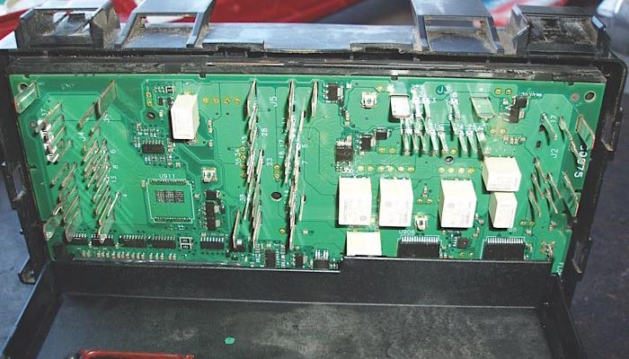
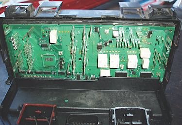
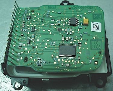
P4191483 (TIPM Circuit board) This circuit control board mounted on the underside of the TIPM fuse and relay box performs most, if not nearly all, electrical switching functions for the Jeep Rubicon..
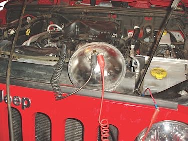
P 4191473 (Head lamp in circuit) To preserve our hearing, we replaced the constantly honking horn with a 5-amp headlamp.
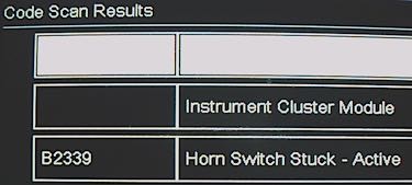
P4211504 (B2339 Horn Switch Stuck-Active) “Horn Switch Suck Active” indicates that B2339 is a hard code that will repeat despite being erased.
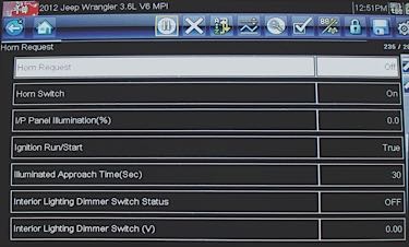
P4211496 (Horn Request Off) The upper line reads “Horn Request–Off,” while the second line reads “Horn Switch–On.” This data indicates that the slave node “sees” a “shorted” horn switch.
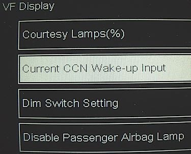
P4211501 (Current CCN Wake-up Input) The CCN “wakes up” when the ignition switch is turned on.
P5291531 (Speed control switch circuit board) The speed control switch contains a “slave node” that transmits data to the Cab Compartment Node or “master” node located in the instrument cluster.