This month’s Diagnostic Dilemma is about the technical and professional issues involved with attempting to diagnose an extremely random no-cranking complaint on a 2003 GMC Yukon equipped with the 5.3L VIN Z engine and automatic transmission. I use the word “attempting” because if we get authorization to proceed in the next thirty days, I have to devise a diagnostic strategy that can pinpoint the source of the random no-cranking complaint.
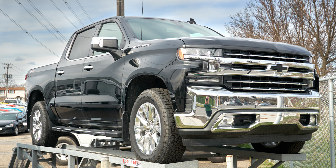
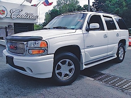
P6101042 (2003 Yukon engine)
Random drivability complaints are a major headache for any diagnostic tech because once the repair is made, he really has no sure-fire method of verifying his repair. Unless the random complaint happens to be a known pattern failure with a known fix, the diagnostic tech often finds himself making an educated guess. Many diagnostic techs are willing to spend a few days commuting with the vehicle from home to work with his scan tool attached in the recording mode. But if that isn’t successful in helping determine the problem, all else depends upon the owner’s willingness to engage in a process that might yield no results.
2003 Tahoes and Yukons: So far this year, I’ve dealt with three different 2003 General Motors Tahoe and Yukon platforms with between 130,000 to 170,000 miles on the odometer. This month’s Diagnostic Dilemma is about the first 2003 Yukon, which was unloaded at my client shop’s drive with an apparent no-cranking, no power to the instrument panel condition.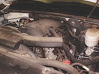
This vehicle, which is owned by a school district in a neighboring county, fully illustrates the complexities created by a random no-cranking complaint. The problem initially began early in November 2014 when my client’s shop was called to troubleshoot a no-cranking problem on the Yukon, which had failed only blocks from his shop. According to the shop’s repair order, the Yukon wouldn’t communicate with the scan tool and no information appeared on the instrument cluster other than a low-fuel warning light. All other accessories and modules operated as they should. After the Yukon was hauled to my client’s shop, it started and ran perfectly. No diagnostic trouble codes (DTCs) were present, and the odometer indicated 167,261 miles. Additionally, the tow truck driver reported that the left-hand driver’s door window wouldn’t budge from the “down” position. Considering the advanced mileage, an appearance of a P1518 DTC, and the presence of only 9 volts on several underhood fuses, the client’s shop decided to replace the ignition switch.
The Second Visit
On January 16, the Yukon reappeared in the shop’s driveway and, as you might suspect, it started and ran perfectly after it was unloaded from the car hauler. A P1518, U1000 and U1160 was recorded. The shop owner drove the vehicle for several weeks with the scan tool attached, but with no results. At this point, the driver’s door window operated only when the door was partially open. More to the point, service records indicated that the Yukon had rolled up an additional 1,384 miles since the new ignition switch had been installed.
At that point, my phone rang and I became involved in The Case of the Great 1,384-Mile Test Drive. I’ll summarize by saying that, not able to duplicate the complaint, we eliminated most of what I call the “stupid stuff” by cleaning the throttle body and applying Stabilant-22 to the TAC module and throttle body connectors. In addition, we also checked all powers and grounds and wiggle-tested ground splice 103 and ground 103 in the main engine harness at the right rear of the cylinder head. To address DTCs U1000 and U1160, we repaired a broken ground wire on the driver’s door module. But, as mentioned above, we had no way to verify those repairs.
The P1518 DTC
The P1518 DTC is pivotal to my diagnosis since it has appeared in several case studies of the 2003 Tahoe/Yukon platforms. To paraphrase service data: The Powertrain Control Module (PCM) and Throttle Actuator Control (TAC) module communicate with each other through a separate serial data wire that is apparently isolated from all other data circuits. Good circuit integrity as well as adequate system voltage is required to transmit or receive serial data between the PCM and TAC module. DTC P1518 can also set if the battery voltage is low, which throws another curve into my diagnostic process.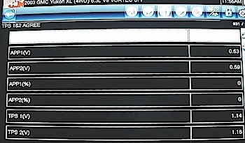
P6090120 (TPS 1&2 Agree)
According to service data, this diagnostic test monitors the accuracy of the serial data exchanged between the PCM and TAC module. If the PCM detects invalid data or a loss of data between the PCM and TAC module, a P1518 DTC will be stored in the PCM’s diagnostic memory. The enabling conditions for P1518 include the ignition switch being turned on and the ignition switch voltage being more than 5.23 volts for more than one second.
Since P1518 includes five pages of diagnostic tips and a 29-step testing procedure, I won’t attempt to summarize that information in this space. But these diagnostic steps are generally designed to diagnose hard failures. More important, P1518 will turn off the malfunction indicator light if the diagnostic monitor runs and doesn’t detect a failure during three consecutive ignition cycles. A current “last test failed” clears when the diagnostic runs and passes. A history P1518 clears only after 40 warm-up cycles “if no failures are reported by this or any other emission-related diagnostic.”
Electronic Amnesia?
At this point, I asked for a complete description of the failure from the fleet manager, who happened to be backing out of a parking space when the engine stalled. The manager responded that it was a stalling, no-crank condition and neither the instrument cluster nor the transmission selector PRNDL indicator showed any data. As with the original failure in November, the low fuel level warning light was the only warning light showing on the instrument cluster.
After the Yukon rolled off the car hauler, I immediately scanned for DTCs and polled all modules for communications failures. As I suspected, all modules including the PCM were communicating with the scan tool. But oddly enough, there no DTCs were stored in the “history” or the “failed this ignition” memories.
At this point, I turned the ignition key and the engine started instantly. Surprisingly, my scan tool indicated a DTC present, which was the now-familiar P1518 DTC in the “failed this ignition” memory. Considering how P1518 is stored and cleared, I currently believe that the PCM might be suffering from a case of electronic amnesia when a loss of either power or ground erases its diagnostic memory. And, interestingly enough, another 1,300 miles had elapsed since the Yukon’s second visit in January.
The Test Drive: After being parked for a month, my diagnostic client decided to take the Yukon for a test drive with scanner attached. The Yukon suffered a severe loss of power before it left the parking lot. My client had time to capture four different movies of the PCM’s data stream. Pertinent data includes: 1) The TAC is operating in the Reduced Power Mode. 2) TPS1 sensor desired angle 9 percent, TPS1 indicated angle 100%. 3) APP 1 0.53 volts and APP 2 .059 volts. 4) APP I & 2 agree, 5) TPS2 indicated angle 26%. 5) Engine 819 rpm, desired is 550 rpm. 6) Engine load 7 percent. 7) MAF 13.99 grams per second. 8) Ignition 12.9 volts.
P6091031 (Engine Speed)
Reviewing the Data
Obviously, we didn’t have any hard data to work with until the Yukon’s third visit. At that point, I found no DTCs in any of the PCM’s diagnostic memories. Presumably, the towing company had to turn the ignition switch on several times to load and unload the Yukon, but that shouldn’t have cleared the P1518 from the history codes, which leads me to the possibility of the PCM clearing its own memory by losing power or ground. The PCM has one B+ Keep Alive Memory feed, and five grounds feeding into splice #103 inside the main engine harness and terminating at G103 at the rear of the right-hand cylinder head. So there are a possible five pins at which power or ground can fail.
As for issues with the serial data, the reduced power mode and DTC P1518 indicate problems with communications between the PCM and TAC modules. Indicated engine speed is 815 rpm while desired speed is 550 rpm. The MAF is 13.99 grams per second, which is high for a 5.3-liter engine idling at 815 rpm. The ignition PID indicates 12.9 volts, which is low for an engine running at 815 rpm. Throttle position, on the other hand, is 9 percent desired, but 100 percent is indicated. Four more short movies were recorded, with some showing no problem and others showing open loop and no O2 sensor voltage with heaters on.
P6211073 (Open/Closed Loop)
At this point, we also have to keep in mind that the update rate on a large number of PIDs is probably pretty slow, which in itself could possibly create some of these data anomalies. Last, but not least, the stalling, no-crank, no instrument cluster data problem wasn’t duplicated on this 20-minute test drive through the parking lot.
Lessons Learned
Some shops won’t take a random failure drivability complaint because they simply can’t duplicate the problem. Obviously, this Yukon belongs to a public fleet account, so my client shop might pursue this problem to help his account. On the other hand, the fleet account might scrap the vehicle rather than attempt another repair. As for casual walk-in customers, doing anything beyond performing an initial scan of the system electronics and a TSB/case history search can turn into a real money loser for the shop because there’s no predictable outcome to the diagnosis or repair. It’s a tough situation that’s going to become more common as the technical complexity of our national vehicle fleet increases and the average vehicle age and accumulated mileages begin to inch up.
P6091036 (TAC/PCM Fault)
Another 1,300-Mile Test Drive?
If authorized, I’ll begin by removing each of the PCM fuses one-by-one to see if I can duplicate the no-crank, no-communication, no-instrument cluster data issue. Next, I’ll check the pin 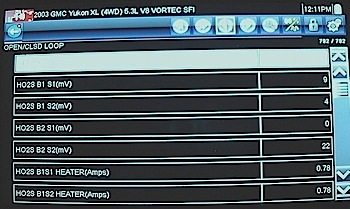 fit on the C1 and C2 PCM connectors. Maybe some new information or discoveries will show up in the meantime. I may also use a lab scope to monitor inconsistencies or failures in the bus wire between the PCM and TAC. Another bit of history information involves the failure occurring when the vehicle faces into the sun on warm days. Assuming that the school district wants to spend money on another attempt to diagnose the stalling complaint, and assuming that we get our diagnostic strategy fully developed, we’ll be ready for another 1,300-mile test drive. Either way, I’ll keep you posted.
June 15, 2015
P6101042 (2003 Yukon engine) The Tahoe/Yukon platforms are very popular in the Rocky Mountain area. Unfortunately, a few “unsolvable” problems are beginning to pop up.
P6090120 (TPS 1&2 Agree) Although a TAC error was indicated, the APP and TP data now agree.
P6091031 (Engine Speed) Notice that the MAF sensor grams per second is nearly three times normal for a 5.3-liter engine at 819 rpm.
P6211073 (Open/Closed Loop) In this frame, the upstream and downstream O2 sensor voltages have dropped to nearly zero, which has driven the fuel management system into open loop.
P6091036 (TAC/PCM Fault) Notice that the TP desired angle is 9 percent while the TP indicated angle is 100 percent.
Hybrid Safety
When many technicians first consider servicing hybrid vehicles, the high-voltage levels may cause them to become apprehensive. But the fact is, hybrid vehicles are extremely safe to service. There are many safety devices in place, in many cases double, and even triple the amount of redundant safety devices to prevent contact with high-voltage circuits. To date, there have been no reported injuries or deaths from contact with the high-voltage system in a hybrid vehicle. This is not to say that it is impossible to get electrocuted. Always follow the listed safety procedures when performing high-voltage service.
Class 0 high-voltage gloves should be kept on hand for the occasions when high-voltage service becomes necessary or when de-powering the high-voltage system in any hybrid vehicle. These gloves are rated for up to 1,000 volts and should be tested for leaks before and after each use. To test the insulating gloves for leaks, simply trap air in the glove and roll the glove up starting at the cuff to compress the air in the glove. Watch and listen for leaks.
In the event a high-voltage component is being serviced, leather over gloves should be worn to protect the delicate rubber-insulating glove. To recertify these gloves, they must be returned to the manufacturer for further testing. Recertification must take place every six months after the gloves are placed into service or every 12 months after initial purchase if the gloves are not used. High-voltage gloves must be kept dry at all times. In the event the gloves become moist with perspiration, specific high-voltage glove powder should be used to ease glove application and removal. Talcum powder should not be used due to its potential for electrical conductivity.
High-voltage gloves should never be folded or stored on a counter or shelf. Always store these gloves in their original, non-conductive storage bag. Place the gloves in the bag open-end down and hang the bag in a safe place. The non-conductive bag should be equipped with ventilation holes on the bottom and a storage hook on the top or back.
High-voltage gloves do not need to be worn when performing general maintenance services. These are available from most professional electrical suppliers, tool and equipment distributors and professional auto parts suppliers.
Other Hybrid Safety Tips
Other safety tips that apply to all hybrid vehicles include:
- If you intend to service the high-voltage motor on a hybrid vehicle, and this includes removing the transmission, don’t wear watches or rings. The permanent magnets found in the rotor of the brushless DC motors are very powerful.
- Due to the extra strong magnetic fields produced by the high-voltage components, service should not be attempted if you have a pacemaker.
- Always test for the presence of high-voltage before you touch or disconnect any high-voltage component. Use a quality multimeter capable of reading at least 600 volts AC (see manufacturer’s recommended procedure).
- Hybrid vehicles can start the internal combustion engine automatically anytime the ignition is on. Some hybrid vehicles can auto-start if the key fob is within 15 feet of the vehicle and the vehicle is in READY mode. Ensure the hybrid system is properly powered down prior to service. A hybrid vehicle left in READY mode may start at the most inopportune time.
- A hybrid vehicle should never be towed with the drive wheels on the ground because the motor/generator will create voltage any time the drive wheels are turned in the same direction. This also goes for pushing the vehicle around the shop; however, very slow speed or short distance pushing or pulling like when a vehicle is winched onto a flatbed is considered safe.
By Chris Chesney, senior director of customer training at Advance Professional’s CARQUEST Technical Institute.