Models affected: 2011 and prior GM passenger cars and trucks
This repair can be applied to any electrical connection including, but not limited to: lighting, body electrical, in-line connections, powertrain control sensors, etc. Do not over apply lubricant to the point where it prevents the full engagement of sealed connectors. A light coating on the terminal surfaces is sufficient to correct the condition.
Some customers may comment on any of the following conditions:
– An intermittent no crank/no start;
– Intermittent malfunction indicator lamp (MIL) illumination;
– Intermittent service lamp illumination; and/or
– Intermittent service message(s) being displayed.
The technician may determine that he is unable to duplicate the intermittent condition.
Cause: This condition may be caused by a buildup of nonconductive insulating oxidized debris known as fretting corrosion, occurring between two electrical contact surfaces of the connection or connector. This may be caused by any of the following conditions:
– Vibration
– Thermal cycling
– Poor connection/terminal retention
– Micro motion
– A connector, component or wiring harness not properly secured, resulting in movement
On low current signal circuits this condition may cause high resistance, resulting in intermittent connections. On high current power circuits this condition may cause permanent increases in the resistance and may cause a device to become inoperative.
Representative List of Control Modules and Components
The following is only a representative list of control modules and components that may be affected by this connection or connector condition and does not include every possible module or component for every vehicle.
– Blower Control Module
– Body Control Module (BCM)
– Communication Interface Module (CIM)
– Cooling Fan Control Module
– Electronic Brake Control Module (EBCM)
– Electronic Brake and Traction Control Module (EBTCM)
– Electronic Suspension Control (ESC) Module
– Engine Control Module (ECM)
– Heating, Ventilation and Air Conditioning (HVAC) Control Module
– HVAC Actuator
– Inflatable Restraint Sensing and Diagnostic Module (SDM)
– Any Air Bag Module
– Seatbelt Lap Anchor Pretensioner
– Seatbelt Retractor Pretensioner
– An SIR system connection or connector condition resulting in the following DTCs being set: B0015, B0016, B0019, B0020, B0022 or B0023
– Powertrain Control Module (PCM)
– Remote Control Door Lock Receiver (RCDLR)
– Transmission Control Module (TCM)
Correction:
Do not replace the control module, wiring or component for the following conditions:
– The condition is intermittent and cannot be duplicated.
– The condition is present and disconnecting and reconnecting the connector can no longer duplicate the condition.
Use the following procedure to correct the conditions listed above.
1. Install a scan tool and perform the Diagnostic System Check – Vehicle. Retrieve and record any existing history or current DTCs from all of the control modules (refer to SI).
– If any DTC(s) are set, refer to the DTC List – Vehicle to identify the connector(s) of the control module/component that may be causing the condition (refer to SI).
– If DTCs are not set, refer to Symptoms – Vehicle to identify the connector(s) of the control module/component that may be causing the condition (refer to SI).
2. When identified, use the appropriate DTC Diagnostics, Symptoms, Schematics, Component Connector End Views and Component Locator documents to locate and disconnect the affected harness connector(s) that are causing the condition.
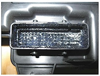
Note: Fretting corrosion looks like little dark smudges on electrical terminals and appear where the actual electrical contact is being made. In less severe cases it may be unable to be seen or identified without the use of a magnifying glass. See Figure 1.
Important: Do not apply an excessive amount of dielectric lubricant to the connectors as shown, as hydrolock may result when attempting to mate the connectors. Only use a clean nylon brush that is dedicated to the repair of the conditions in this bulletin.
3. With a 1” nylon bristle brush, apply dielectric lubricant to both the module/component side and the harness side of the affected connector(s).
4. Reconnect the affected connector(s) and wipe away any excess lubricant that may be present.
5. Attempt to duplicate the condition by using the following information:
– DTC Diagnostic Procedure
– Circuit/System Description
– Conditions for Running the DTC
– Conditions for Setting the DTC
– Diagnostic Aids
– Circuit/System Verification
– If the condition cannot be duplicated, the repair is complete.
– If the condition can be duplicated, then follow the appropriate DTC, Symptom or Circuit/System Testing procedure (refer to SI).
Courtesy of Mitchell 1.