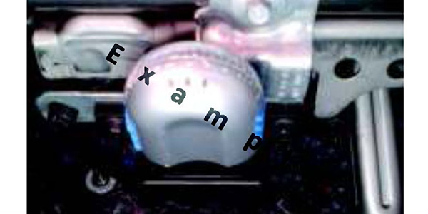
When addressing a module “No Communication” related issue, it is important to perform a visual inspection of the vehicle in various locations. This will help identify potential tampering, modifications or the presence of aftermarket electronic add-ons. Devices connected to the DLC that can affect communication network functionality include:
• Aftermarket remote start system;
• GPS tracking device;
• Idle control device;
• Powertrain monitoring device;
• Performance programmer; and
• Insurance data logging device (see Figure 1).
All aftermarket devices or systems that are connected to the communication network must be disconnected and the network retested for operation.
When there is no communication with the vehicle and scan tool is not capable of starting an automated session, a manual entry vehicle session must be started using the PCM Tear Tag number (see Figure 2).
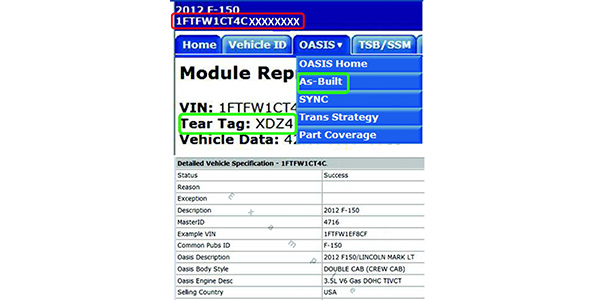
This will allow the IDS to start a session for the appropriate vehicle and powertrain configuration. The four-digit tear tag number can be found using the IDS by double-clicking on the VIN at the top left corner of the blue PTS banner to display the “Detailed Vehicle Specification.”
During the network test, the IDS scan tool sends a request or “pings” all modules on the network and looks for a response back. Modules that do not respond back are labeled as “FAIL.” Modules that do respond back are then asked to report any DTCs (U-codes). A module can have no calibration loaded or be considered “blank” and still “PASS” the network test.
Modules reporting a “FAIL” on the Network Test can be due to:
• Network interference from an aftermarket device.
• Vehicle is not equipped with that feature or optional equipment. No power or ground to the module.
• One or both communication circuits (Bus+/-) open or shorted (together, to power, to ground).
• Internal module hardware failure.
• This not only can affect one module’s ability to report during the test, but can also affect multiple modules on that communication network.
• A module that “FAILS” can also cause other modules to report no communication DTCs, putting false blame on good modules.

Topology
The Network Topology map for every vehicle can be found in service information (see Figure 3). The Network Topology map can be used for identifying the modules on a given network. Look for the modules with the 120 ohm terminating resistors.
When addressing network concerns, the wiring diagram should always be used. This will help with identifying common connectors within a given leg of the network that may be suspect.
Network Resistance Check
The battery must be disconnected when measuring resistance in the network. Each CAN network has two terminating modules that contain a 120 ohm terminating resistor. When the total network resistance is measured at the DLC, the resistance should be between 54 and 66 ohms. If only one resistor is present, the resistance will measure 120 ohms. When both terminating modules are removed from the network, the resistance reading should be 10,000 ohms or greater.
Any remaining resistance can suggest that a module on the network has an internal fault or the circuits are shorted together. If an internal module fault is suspected, the modules can be unplugged one at a time and the total resistance checked again to see if the faulty module has been isolated.
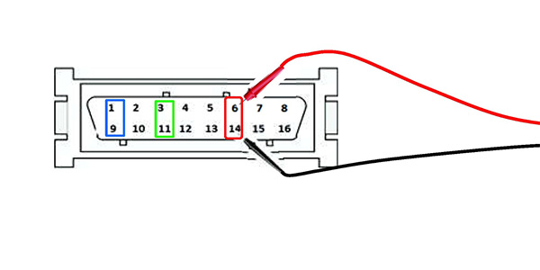 Each CAN network has two circuits with positive and negative connections. Test the circuits with the negative (black) probe in pin 4 (ground) and the positive (red) probe into one of the CAN + and – circuits. The data + (RED) and data – (BLUE) circuits are each regulated to approximately 2.5 volts during neutral or rested network traffic. As messages are sent on the data (+) circuit, voltage is increased by approximately 1.0 volt when a message is sent.
• The data + circuit should see between 2.5v and 3.5v, depending on traffic signals being sent by each module.
• The data – circuit should see between 1.5v and 2.5v, depending on traffic signals being sent by each module.
Tips
• Disconnecting and reconnecting the battery for approximately five minutes (hard reset) may resolve a network concern. This should allow any module locked in a particular state to reset and return to normal operation.
• Power, ground and communication circuit integrity are the essential items needed to support a module’s ability to communicate on the network.
• If disconnecting and reconnecting a specific module resolves or changes the concern, there is likely a connection or circuit issue in that location that requires closer inspection. It is possible for a faulty module to create network faults that can place false blame on other modules.
• Failed modules that “FAIL” the network test need to be addressed first.
This will aid in understanding which networks are affected based on the modules that FAIL and the fault codes that are reported. Carefully follow the appropriate pinpoint steps and document all results. Be sure you understand which modules and CAN Networks with which the vehicle is equipped or not equipped.
• When checking connections, be sure to look for terminal spreading, terminals not locked into the connector cavity and for signs of moisture that could influence intermittent faults.