ECU Diagnostics: 1976 Datsun (Nissan) 280Z
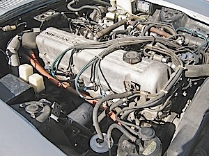
Call me old-school, but imagine my surprise this spring when a retired “friend of a friend” car collector called about diagnosing a 1976 Datsun (Nissan) 280Z sports car. The collector purchased the 280Z (which had been sitting idle with an engine that wouldn’t start) from a Toyota shop, and had several area import shops attempt to diagnose the car with no results. Since the owner mentioned that he had the factory shop manual for the car, I agreed to take on the job. Other than the fuel pump and engine control unit (ECU) having been replaced by the owner, the 280Z was in complete and original condition. It also had two extra ECUs lying in the back seat that had been used for “testing.”

But I thought there had to be a bigger issue here because, with a factory shop manual at hand, other shops had failed to diagnose the 280Z’s cranking, no-start problem. Adding to the bigger picture, changing parts to solve a no-start problem is a familiar story, even on the latest-model imports. After all, we’re dealing with basic electricity, not the proverbial and oft-quoted “rocket science.” Understanding how to use wiring schematics and the full capabilities of a modern digital volt-ohm meter are essential for diagnosing cranking, no-starting problems on the latest-model import cars. So, with this bigger picture in mind, let’s return to the basics of diagnosing a common cranking, no-start problem, be it on the venerable 280Z, or on the latest generation of electronic fuel injection sports cars.
Wiring Schematics
The 280Z’s fuel injection schematics were printed on one page in black and white and the wires were numbered rather than color-coded. In comparison, today’s fuel injection systems are typically printed on as many as six pages. Colored wiring schematics, power distribution charts, ground distribution charts, splice charts, connector charts and component location charts are used to augment the basic engine wiring schematics (see wiring schematic).
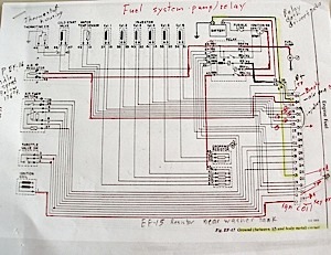
While I’m at it, I want to emphasize that, while the illustrations in the 1976 shop manual didn’t always correspond with the actual vehicle, they do enable a technician to reverse-engineer the fuel injection system. The above schematic shows, for example, that this engine is equipped with non-feedback fuel injection (no oxygen sensor) that also doesn’t have an on-board diagnostic system. Sensors include a throttle valve switch, mechanical airflow meter, thermo-time switch and coolant temperature sensor. Actuators include an air regulator for idle speed control and a main relay that powers the fuel pump, fuel injectors and engine control module. The main relay is activated by the ignition switch, which is protected by a fusible link.
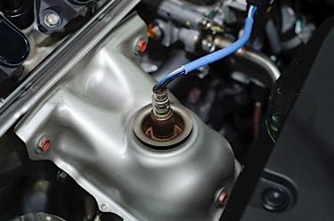
With that said, I found nothing in the shop manual to indicate how the fuel injectors are timed. I might have used a labscope to determine if the injectors are timed or the constant-injection types, but that information wasn’t necessary to diagnose the problem. Since ECU pin number one is attached to the ignition coil negative, the ECU is evidently looking for an ignition signal before it activates the fuel injectors.
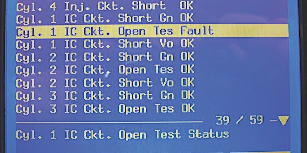
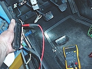
The 280Z’s electronics are connected by non-weatherproof, banana-plug connections. The engine compartment also contains at least four component grounds, which I cleaned as a preventive measure. This done, I was able to verify all of the sensor and actuator circuits by measuring pin-to-pin resistance through the ECU connector, and compared them to the resistance values included in the shop manual. As for power to the ECU, key-on power is supplied to ECU pin 20. Since the ECU has no diagnostic or adaptive memory, a keep-alive battery power terminal isn’t required (see photo 2).
Diagnosing Fuel Delivery
To test the ignition system, I introduced propane into the air intake while cranking the engine. The engine immediately started and kept running as long as I supplied propane. In theory, when the Bosch mechanical airflow meter detects air flow through the engine, a mechanical switch should close to keep the fuel pump running.
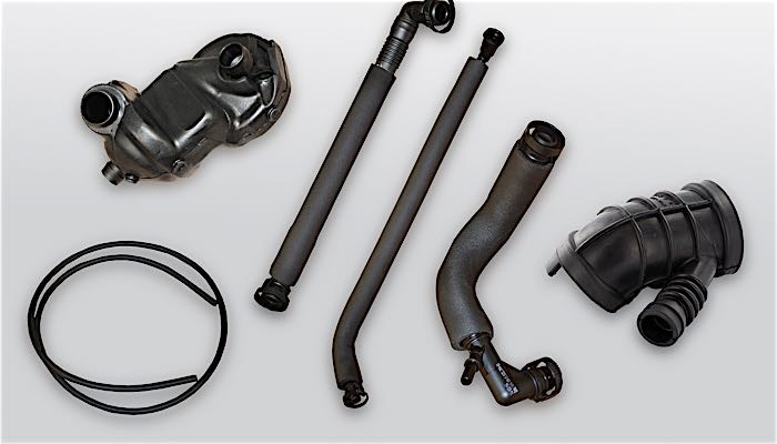
At that point, I spliced a fuel pressure gauge into the injector rail and noticed that the fuel pressure would rise enough to momentarily start the engine, but not keep it running. So, the new fuel pump installed by the customer likely had an intermittent power or ground problem. (See photo 3)
My next step was to see if the fuel injectors were pulsing. The main relay powers the ECU, fuel injectors and fuel pump. Current flows from main relay pin 4 to ECU pin 4 to signal the cranking mode. ECU pin 34 activates the cold-start injector by grounding the injector circuit. Remember that the cold-start injector is controlled by the thermo-time switch, which allows fuel only when the engine is cold. Going to the fuel injectors themselves, pin 43 from the main relay powers a set of six dropping resistors. Current flows directly from the dropping resistors to the fuel injectors. As with most modern systems, the injector opens only when the ECU injector driver grounds the injector circuit.
Ground Circuit Diagnosis
After removing a fuel injector connector, I measured voltage at both pins, which indicated that the ECU wasn’t grounded to battery negative. Going back to testing voltage at the main relay and ECU pins, I measured voltage values ranging from battery voltage to just one or two volts, which is indicative of one or more open ground circuits in the ECU. This low-voltage phenomenon is called ground-looping or back-feed, and, in this case, is caused by voltage seeking a ground through the ECU.
Given the above operating scenario, the presence of voltage at both injector pins indicated that the ECU wasn’t grounded to the negative battery terminal. I also noticed that two large red wires were attached to the battery positive terminal and that the battery negative cable had an open connector bay. One red wire attached to the battery positive terminal appeared stock. The other red wire looked out-of-place because it apparently had a connector removed and the insulation scraped away. Could it be that this red wire was actually the missing ground connection? If so, this red wire should show battery voltage when removed from the B+ terminal connector.
When tested with a DVOM, no voltage was apparent at the wire’s end, which indicated that an open circuit existed somewhere in the ground circuit itself. Grounding the wire with another jumper wire produced no change. To further complicate matters, the schematic indicated that pins 72 (main relay), 49 (coolant temperature sensor), 5 (ECU ground), 16 (ECU ground), 17 (ECU ground) and 35 (ECU ground) were spliced into this single red wire somewhere inside the main wiring harness.
Lacking a splice chart, I began stripping the wiring harness and finally found six blue wires spliced into the single red wire on the engine side of the firewall.
Evidently, a mechanic in the distant past had interpreted “red” as the “color code” for battery positive and attached the ground to battery positive. The ground had been attached to the positive battery terminal for so long that acid had leached through the wiring harness and corroded the splice connector, which is why I couldn’t detect key-on voltage at the end of the wire. Installing a new splice connector and attaching a new black ground wire to the battery negative terminal allowed the engine to instantly start.
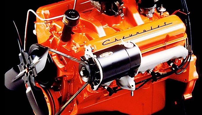
During warm-up, a rough engine indicated that several fuel injectors were slightly fouled. That mild condition was remedied by adding fuel injection cleaner to five gallons of fresh gasoline. Compression and base ignition timing were at specification even as the base idle speed needed some slight adjustment. When I finished, the venerable six-cylinder 280Z engine would start on the first revolution.
Other Ground Circuit Diagnostic Tips
A borderline ground circuit can result in an intermittent (repeatable) or random (non-repeatable) component malfunction. The major influences are changes in temperature, humidity and electrical load through the ground connection.
Since ground resistance varies according to temperature, humidity and electrical load, a bad ground circuit can cause multiple trouble codes to be stored at random in the diagnostic memories of the engine, body-control and other modules.
A bad ECU ground can produce odd voltage readings at the key-on fuses located in the engine compartment or instrument panel fuse boxes. These fuses should be within 0.5 volts of battery voltage.
Remember that ECU reference voltages normally measure about 5, 8 or 12 volts. If voltages ranging between these values are measured at the ECU, a grounding fault might be present.
Voltage-drop testing is one indicator of ground condition. Voltage drop is measured by attaching a voltmeter in parallel between the ends of the circuit in question. To test an engine ground, attach to a clean mounting point on the engine block and to the battery negative post. According to Ohm’s Law, the actual voltage drop will vary with amperage flow across the faulty ground connection. Therefore, the rule of thumb for high-amperage circuits like the starter or alternator is 500 millivolts (mV), while the rule for low-amperage circuits like the ECU ground is 50 mV or less.
When dealing with intermittent codes or failures, clean and re-torque all of the major grounds, including the engine block ground, and seal them with an anti-corrosion compound. Sheet metal grounds used for grounding exterior lighting, HVAC and other components are always the most vulnerable.