Understanding ECM Issues on a 2003 GMC Yukon
ECM diagnostics can be a challenge because you often find yourself working after the fact. As described in the July 2015 issue of Underhood Service (“The 1,300-Mile Test Drive”), a seemingly routine loss of power and a no-cranking, no-instrument cluster, no-scan-tool communication complaint on a 2003 GMC Yukon, VIN Z 5.3-liter flex fuel engine turned out to be a major Diagnostic Dilemma. The Yukon, which is owned by a neighboring public school district, failed to start in November 2014. The first Diagnostic Dilemma occurred when the Yukon started and ran perfectly after it was delivered to my client’s shop. A DTC P1518 was stored in the history codes, which my client’s shop diagnosed as a bad ignition switch. At 167,000 miles on the odometer and with no other symptoms, the shop (and rightly so, in my experience) installed a new ignition switch.
The second Diagnostic Dilemma occurred when the Yukon returned in January 2015 with a loss-of-power complaint with another P1518 recorded. The loss-of-power complaint couldn’t be duplicated so, to cover our bases, we voltage-dropped all powers and grounds and cleaned the throttle plate and body. We also applied Stabilant-22 to enhance the electrical conductivity of the Throttle Activation Control (TAC) module and throttle body connector pins. In May 2015, the Yukon experienced another no-cranking, no-start, and instrument cluster failure and again arrived via tow truck at my client’s shop. Immediately after delivery, I discovered a clean diagnostic memory in all modules, which was especially odd since 40 engine warm-up cycles are required to erase the ever-present P1518. Oddly enough, each of these failures occurred at approximately 1,300-mile intervals, making each a very random incident.
Replacing the ECM
This third Diagnostic Dilemma was postponed until the school district began its fiscal year in July. By now, I had collected a thick folder of case studies and diagnostic information on the Yukon and the P1518 DTC. Fortunately for us, the Yukon went into Reduced Power mode before leaving the parking lot on its first test drive. Clearly, the TAC module was dropping into a Reduced Power mode.
Included among the diagnostic trouble codes was the now-familiar P1518. Additionally, there were random U1000 codes, ABS codes, etc. that were indicative of a bad ground. But, I also noticed among the data anomalies a 12.0- to 13.0-volt reading on the ECM engine data stream, which conflicted with a 13.5-volt reading on the Body Control Module (BCM) data stream. After measuring charging voltage at the battery, it was clear that the BCM voltage was correct and the ECM voltage was incorrect.
After bringing the Yukon into the shop, we couldn’t duplicate the loss-of-power complaint. But, since the data stream anomalies continued to bother me, we used a back-up lamp drawing 2.5 amps of current to load the circuits. The power pins flowed 2.5 amps and the ground pins drew 2.5 amps. (If I had to do that test again, I would have used a larger-amperage lamp and measured the ECM’s amperage flow with the engine running at the ECM’s G103 ground.) Tapping on the ECM or TAC modules or warming them up wouldn’t initiate a failure. So, to paraphrase the immortal words of Yogi Berra, we reached a fork in the road and we took it by replacing the ECM.
Rolling the Dice
Most ECM diagnostics involve the process of elimination. In other words, when all the sensors, actuators and wiring circuits pass their respective testing, we’re basically down to replacing the ECM. The ECM and the TAC module are linked via a dedicated class 2 bus wire, which might explain the Reduced Power complaint and the P1518 DTC. The second complaint, which was a no-cranking, no-start, instrument cluster failure and a complete lack of trouble codes could be caused by the ECM simply dropping offline through a loss of power or ground.

But, the logic is simple: the ECM commands the starter relay to crank the engine and, with the exception of the voltmeter being sourced from the ignition switch, the operating information displayed on the instrument cluster is relayed to the cluster via a data bus from the ECM. The discrepancy between the voltage shown on the engine data stream and the indicated voltage on the voltmeter and BCM data stream was, at least to me, strongly indicative of a bad ECM. (Replacing the ECM is also included in step 27 of the 29-step diagnostic process required to correct a P1518 trouble code.) Finally, at this point in the diagnosis, replacing the ECM appeared to be a cheaper option than spending countless diagnostic hours chasing “ghost” trouble codes.
Hard-Failure Conditions
In this case study, we had two separate complaints: a loss of power and a loss of ECM functions, including storing codes. Surprisingly, after the new ECM was installed, the TAC module immediately went into the “Reduced Power” mode as the ignition was turned on. Two DTCs appeared: P1515 (variation between commanded and actual throttle position) and P2135 (TP2 disagrees with TP1 by more than 7.5%). P1515 and P2135 are set only when our familiar P1518 is NOT present, which would explain why these two codes hadn’t yet appeared. Long story short, and despite the codes being cleared and B- being disconnected, P1518 had vanished and the TAC was going into limp mode each time the ignition was turned on.
A Vanishing P1518 DTC?
To avoid tying up a service bay with more diagnostics, I drove the Yukon in limp mode to my own shop, which allowed me to pursue the diagnosis at a more leisurely pace. On the positive side, the long-standing P1518 DTC had not set since the ECM had been replaced. On the negative side, the Yukon was now in a hard-failure Reduced Power mode, and the P1515 and P2135 codes are now repeatable DTCs.
Looking at ground distribution, the ECM had four grounds terminating in splice S103. S103 terminates into a single wire that is grounded to the rear of the right-hand cylinder head at G103. As mentioned previously, splice S103 passed testing with a 2.5-amp load. The alternator and starter are grounded through G105, located at the left front of the engine. Grounds G103 and G104 (and the body-to-engine ground cable) also ground feed through G105, which proved to be the critical clue in this month’s Diagnostic Dilemma.
Of course, the accessibility of grounds G103 and G104 is made difficult by a fiber/metallic heat shield wedged between the engine and body. The block ground, G105, is similarly difficult to access since it disappears under the engine and is boxed into a hole formed by the engine mount, timing cover and front differential. Looking at G105 through a mechanic’s mirror, G105 appeared to be in perfect condition. But I had to pull the proverbial rabbit out of the diagnostic hat, so I began by loosening the retainer bolt on G105, which, in this case, turned out to be barely snug. G105 also contained a separate ground wire that is shown in the G105 illustrations, but was not indicated in several different databases.

After removing G105, I found the block surface coated with heavy black paint and the threads of the retaining bolt heavily corroded. Using a small battery-powered Dremel tool with a miniature wire brush, I carefully buffed the paint off the block and cleaned the retaining bolt threads. After all was secured, I coated G105 with an anti-corrosion aerosol. Quite unexpectedly, the engine started and the “Reduced Power” warning instantly disappeared from the Yukon’s vehicle information center. After 7 ½ hours of hot idling and driving time, the ever-present P1518 DTC had also vanished. Case closed? I sure hope so.
The Powers of Grounds
Let’s take a different perspective on the ability of a single ground connection to influence engine performance. Remember that the engine block to battery negative voltage-drop test had passed several times. All of the voltage drops were within the time-honored 500 mV range for 12-volt circuits and 50 mV for 5-volt circuits. So, how could cleaning the engine block ground solve the P1515 and P2135 DTCs and the “Reduced Power” mode?
The answer lies in Ohm’s Law. We know that the voltage drop across a fixed resistance will increase in direct proportion to amperage flow. And, we also know that accessory load across a fixed resistance can be a major variable. So, the question will always be, “How much voltage drop will a particular module tolerate before it fails or sets a code?”
Let’s look at a ground distribution chart for the answer. The Yukon’s ECM shares ground G103 at the right cylinder head with the engine oil level switch, intake air temperature sensor, and park/neutral position switch. Similarly, the TAC module shares G104 at the rear of the left cylinder head with the fuel composition sensor, A/C low pressure switch, A/C compressor clutch, coolant level switch, and under-hood fuse box. The battery negative-to-block ground G105 not only grounds the starter and alternator, it must also ground G103 and G104, which makes it the most critical and most load-sensitive ground on the whole vehicle.
So, the heavily painted block surface forces G105 to ground through the corroded threads of the G105 retaining bolt. While G105 appears fully functional, it’s a bad ground with a loose retainer bolt that is highly susceptible to electrical load. I believe those very qualities created the aforementioned random Reduced Power mode and loss of ECM functions.
I’ll also mention that ECM ground G103 actually broke in two while I was wiggle-testing it. G103 is vulnerable to engine vibration and is a pattern failure. Going back to January, G103 passed a wiggle test. Obviously, a number of strands were broken, but when did the number of broken strands reach a critical point? And, with the added loads of the engine oil level switch, intake air temperature sensor, and park/neutral position switch, could a frayed ground wire cause an intermittent failure of the ECM? It’s anybody’s guess.
ECM Lessons Learned
1) Never trust a voltage drop reading on a circuit that grounds more than one actuator or module because the voltage drop depends very much on peak amperage.
2) All critical grounds should be disassembled, cleaned and coated with an aerosol anti-corrosion compound. Adding a stainless steel star washer can be a plus. Perhaps due to the new ECM having the latest calibrations installed, the Reduced Power mode became a hard failure, which was cured by cleaning ground G105. With that said, I fully understand that not all questions pertaining to this diagnosis are answered in this space. Let’s just say that the outcome of this month’s Diagnostic Dilemma has turned out to be another of the Great Mysteries of the Universe.
GM TSB: Fretting on Connector Causes ON/DTCs Set By Various Control Modules
Models: 2011 and prior GM passenger cars and trucks
Complaint: An intermittent no-crank/no-start condition along with an intermittent malfunction indicator lamp and service message(s) being displayed. The technician may not be able to duplicate the intermittent condition.
Cause: This condition may be caused by a buildup of nonconductive insulating oxidized debris (known as fretting corrosion) occurring between two electrical contact surfaces of the connection or connector. This type of fretting may be caused by vibration, thermal cycling and/or poor connection/terminal retention. On low current signal circuits, this condition may cause high resistance, resulting in intermittent connections.
On high current power circuits, this condition may cause permanent increases in the resistance and may cause a device to become inoperative.
Do not replace the control module, wiring or component for intermittent problems that cannot be duplicated. If you disconnect the module or harness, the condition can no longer be duplicated.
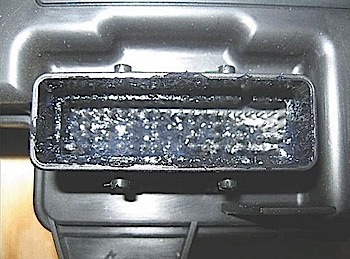
Fretting corrosion looks like little dark smudges on electrical terminals and appears where the actual electrical contact is being made. In less severe cases, this corrosion may be unable to be seen or identified without the use of a magnifying glass. Do not apply an excessive amount of dielectric lubricant to the connectors (as shown above), hydrolock may result when attempting to mate the connectors. Use only a clean nylon brush that is dedicated to the repair of the conditions.