The Chevrolet LT1 engine is the second-generation (Gen II) design of Chevy’s famous small block. The LT1 was fitted in Chevy’s Corvette, Camaro and Caprice/Impala SS. This engine also was used by Pontiac for the Firebird, by Buick for the Roadmaster and by Cadillac for the Fleetwood. The LT1 was first available on the Corvette in 1992, followed by General Motors’ F-body cars (Camaro/Firebird) in 1993 and the B-body cars (Caprice/Roadmaster/Fleetwood) in 1994. The Gen II engine was manufactured in two displacements, 350 cubic inches (5.7L) and 265 cubic inches (4.3L). The 265 cubic inch engine was only available on B-body cars. Interestingly, unlike other Chevy small block designs, the Gen II engine was never available in any trucks manufactured by GM.
Diagnosing 1992-’93 Gen II engines is a little different from 1994 and later Gen II small blocks in that the ’92-’93 units are controlled by a unique ECM. The ’92-’93 engines are controlled by the ECM carrying GM service #16159278. These ECMs utilize a PROM chip for vehicle calibration, and fire the fuel injectors in “batch-fire” mode. The ignition system is GM’s Opti-Spark system. Engines from 1994 and later use the newer flash-style ECMs, which still use the Opti-Spark ignition system, but fire the fuel injectors sequentially instead of batch-fire.
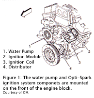 It is important to note that the newer ECMs contain a removable “knock” module underneath a small access cover. The knock module supplies the ECM with the proper ignition retard rate when engine knock is detected. Typically, this module must be removed and installed in the new computer if the old unit is being replaced. Another important difference is the use of a MAF sensor on the ’94 and later models. The 1992-’93 engines used speed-density fuel control, while the ’94 and later models were equipped with a MAF sensor as well as a MAP sensor. The MAP sensor was retained for diagnostic reasons (to compare against the MAF reading and monitor EGR function) and to increase driveability and performance during the “limp-home” mode. The most common areas of failure on the Gen II small block lay in the Opti-Spark ignition system and the cooling system. Figure 1 shows the water pump and Opti-Spark ignition system components mounted on the front of the engine block.
The cooling system on the Gen II engine is a reverse-flow type where the water pump draws engine coolant from the radiator through the thermostat and pumps it up to the cylinder heads and down through the block. Aside from the reverse flow, the unique feature of the water pump is that it is shaft-driven as opposed to belt-driven. The water pump driveshaft is actually gear-driven off the camshaft drive gear. The shaft seal for the water pump is the most common point of failure in the cooling system, and it is usually rather obvious. Leaks may start small, but they get big in a hurry. When replacing a water pump on a Gen II engine, it is usually best to replace the shaft-drive coupling as well. If the coupling is even slightly out-of-round and not replaced, you may end up replacing the water pump a second time somewhere down the line.
 The Opti-Spark ignition system employs a front-mounted distributor that is located below the water pump (watch those coolant leaks!) on the front of the engine block. The distributor is driven directly off the camshaft. Within the distributor are the high- and low-resolution pick-up sensor and timing disk, the rotor and cap. These used to be available as separate components, but are now typically available only as complete assemblies. The Opti-Spark distributor has a small vent for fresh air and, as such, may be susceptible to moisture problems if clogged or exposed.
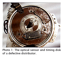
Photo 1 shows the optical sensor and timing disk of a defective unit. The rust on this unit gives away the fact that the optical sensor suffered permanent water damage. The distributor transfers spark energy to the spark plugs from a single ignition coil and module (usually mounted on the front of the left cylinder head).
Figure 2 is a schematic of the Opti-Spark ignition system. Typically, when the Opti-Spark system fails (or is in poor condition), both the fuel injection and the ignition system are affected. The Opti-Spark system relies on two signals generated by an optical sensor pair and a timing disk. The sensors produce a high-resolution signal of 180 pulses per crankshaft revolution (for ignition system accuracy), and a profiled low-resolution signal. The low-resolution signal is profiled so that the ECM can determine the position of the #1 cylinder. The low-resolution profile gives a one-degree pulse every 90 degrees of camshaft rotation, separated by profiled pulses, which are approximately 6, 12, 18 and 22 camshaft degrees in duration respectively, and are also spaced 90 camshaft degrees apart. They occur in alternate sequence, first a short pulse, then a profiled pulse, followed again by a short pulse. Due to the alternating sequence of low-resolution pulses, the ECM receives a low-resolution pulse every 90 degrees of crank rotation.
By studying the timing disk in Photo 1, you can see how the timing slots are laid out. The distributor driveshaft is keyed to reduce the possibility of installing the unit incorrectly and creating timing errors in the signal. Generally, it is the high-resolution signal that is the first to fail. If this occurs, the ECM will generate DTC P0372, but the engine may still run, sometimes seemingly quite well. If the low-resolution signal is lost but the high-resolution signal is present, the ECM will generate DTC P1371. In this condition, the engine will not run, as there will be no fuel pump operation, injector control or ignition fire. The catch here is in the case of an intermittent high-resolution signal. It is possible to get a high-resolution signal that works intermittently, but generates no DTC. If the intermittent misses in the signal occur outside of the low-resolution pulses, the ECM may interpret that as a mechanical running problem and not an electrical/electronic failure of the sensor.
In cases such as this, the use of a scope is the only answer. By pinning the high- and low-resolution signals at the same time, you can easily determine if there is a fault in the sensor assembly. Since the sensors are of the optical type, you can expect a clean square wave signal measuring 5 volts peak-to-peak. If the engine keeps turning over, the high-resolution pulses should just keep coming in a steady square wave.
One other area of consideration when diagnosing Gen II-equipped cars is that of aftermarket performance enhancements. Aside from superchargers and similar heavy modifications that are rather obvious, there are other modifications that are quite popular and may cause diagnostic headaches, but may go unnoticed if you don’t look carefully.
When certain driveability concerns or emission system errors occur, look out for items such as aftermarket performance headers and exhaust systems, fuel pressure regulators, ignition systems and (most troubling) performance software. Remember too, your customer may have bought his Gen II-equipped vehicle used and may not be aware of any high-performance goodies the previous owner may have installed and left on.
Exhaust systems aren’t much of a concern except for 1996 and later OBD II vehicles, where the rear (post-catalytic) O2 sensor may have been tampered with or eliminated in favor of a high-flow exhaust system.
When a set of headers has been added, it should be verified that a contaminated O2 sensor (due to incorrect type or use of silicone) is not causing fuel trim errors. Checking O2 cross-counts with a scan tool or verifying O2 sensor operation with a scope may lead you to a quick fix for fuel trim issues.
The same goes for adjustable fuel pressure regulators. When adjustable pressure regulators are installed and set at too high a pressure, low-speed fueling may suffer with excessively rich mixtures that appear to straighten out as engine speed climbs. High-performance aftermarket ignition systems can cause running problems if not properly installed. Be wary of the routing of electrical harnesses when these ignition systems are used, as the high- and low-resolution signals of the Opti-Spark system are low-voltage/low-current signals. The Opti-Spark system signals can easily be affected by electrical noise and electro-magnetic interference if the wire harness is not properly shielded. Finally, have the customer verify whether or not any modifications have been made to the software calibration. Many aftermarket flash tools exist that allow the end-user a certain amount of adjustability of the fuel and ignition curves.
If you have a driveability problem or Check Engine light on your hands, it may be caused by improper software. Having the customer approve a re-flash of engine software may help in the diagnosis of a particular problem. Naturally, if high-performance software has been installed in the ECM, it may even be prudent to avoid doing any diagnostic work until the OE software is re-installed. After any problems are taken care of, customers can always have performance software re-installed if they so desire.


