 Since the advent of OBD II, every vehicle is equipped with a sophisticated system that measures each cylinder’s contribution to engine power, becoming one of the most difficult challenges we face. Each time a cylinder fires, the misfire monitor uses a highly accurate crankshaft angle measurement to measure the crankshaft position. This system needs to have an accurate crankshaft position sensor that is able to read the crankshaft position, even at high RPM, sending a clear signal to the PCM. Then the PCM monitors the crankshaft acceleration time for each cylinder at the firing time.
A specific crankshaft acceleration time occurs only if a cylinder contributes with normal power. When a cylinder does not contribute to engine power, then it’s misfiring and crankshaft acceleration for that particular cylinder is slowed. It’s important to note that this monitor looks only at the crankshaft’s speed of acceleration during a cylinder’s firing stroke and, therefore, cannot determine if the problem is fuel, ignition or mechanical related.
Misfires are categorized as Type A, B or C. Only a Type A misfire will make the MIL flash while possibly causing immediate damage to the catalytic converter.
When you are diagnosing a misfire DTC, it’s good to ask the customer if the MIL was flashing. Then, after reading the DTCs you will have valuable freeze-frame information to reference, that captures the engine operating conditions whenever the MIL is illuminated. (Each time the ECM reports a misfire, the current engine operating conditions are recorded in the failure records buffer.) Because this is emissions-related information, we are able see and use this information working with a common generic OBD II scan tool.
There are only a few Parameter IDs (PIDs) in the OBD II list, but the most important to duplicate in this failure are engine speed, engine temperature, engine load and vehicle speed. The vehicle speed tells us if we can duplicate the problem at the shop. An engine load higher than 40% makes us think the secondary ignition is weak, and the engine temp tells us if we have to warm up the engine or let it cool down.
The car we are using is a 2001 Mercedes-Benz E320 sedan (210.065) with a 3.2L V6 engine (112.941), and it did not have any problem. We induced a misfire in order to produce the screen shots for this article. Let’s see what the scan tool suggests we do with a DTC P0301 misfire.
The troubleshooter function on the scan tool says to check the power at terminal 2 on the ignition coil and ground at terminal 1. With the key-on, it should have normal battery voltage. If the voltage is too low, it could indicate a problem with too much resistance in the wiring.
Then, the troubleshooter says to check the ignition coil primary resistance between terminals 1 and 3, and compare it to factory specifications.
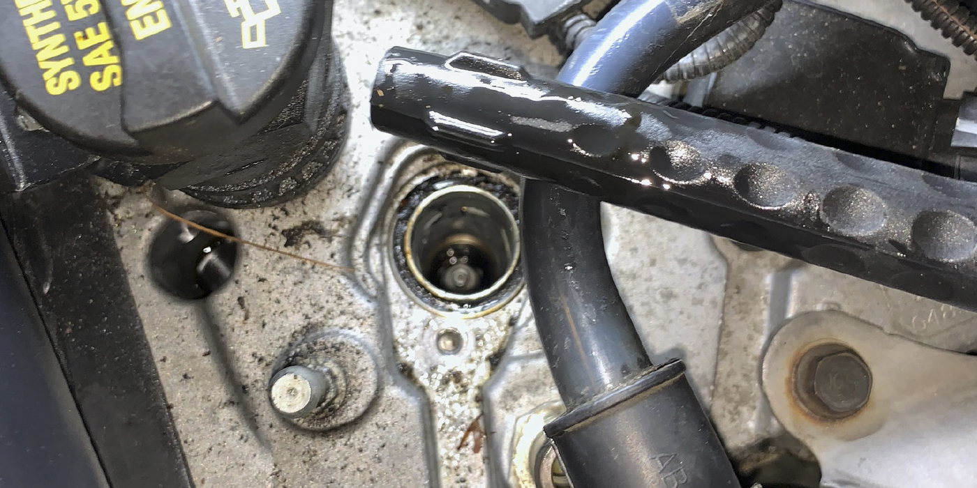
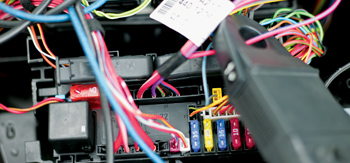
At this point, I assume that the troubleshooter wants the technician to make sure that he’s not losing power or ground at the ignition coil connector, then check the resistance at the ignition coil primary winding. These are good diagnostic checks, but, in some cars, the ignition coils are not easy to access and it takes time to get to them. For some V8 engines, removal of the upper intake plenum is required to check the ignition coil primary resistance. It’s possible to check the resistance values at the ignition coil output terminal relay of the wiring harness, from the relay (Pin 87) that feeds the coils or just from the fuse, if the fuse is located after the relay.

There is a dedicated fuse to power the ignition coils in this vehicle. In other cars, the ignition module is on top of the ignition coil(s) (not in the PCM), so we are unable to check this value because the transistor that grounds the ignition coil is on top of the same coil.
One of the best ways to check primary resistance is to check the ignition coil current using a digital storage oscilloscope with an amp probe. See Diagram 1.
Channel 1 (red), shows that I clamped the current amp probe at 5 amps per division, reading the current around the power through the fuse (6) dedicated for the ignition coils, from the passenger’s-side fuse and relay module box located at the rear side of the engine compartment.
In Channel 2 (blue), I took the primary signal to the same ignition coil at the PCM connector. The pattern starts at the left of the screen and moves to the right, and the amperage builds up as the coil saturates. At this moment, the coil is being charged.
When the coil saturates, the internal module releases the ground. Here is when the primary signal fires, that, in turn, causes the secondary signal to fire. Channel 2 (blue) shows us a clear ignition burn time that lasts almost three divisions considering a good length, and, after that, we have a good oscillation before the ignition coil enters in the cool-down time.
The advantages of using this method are:
• No unplugging of ignition coils;
• No removal of any upper plenum to get access to the coil;
• Connectors were not disturbed; and
• The test was performed with the engine hot and under the conditions described by the driver and the freeze-frame data.

Then, if we slow the time per division in the oscilloscope until we see two pulses in Channel 2 (blue), we are reading two crankshaft revolutions in the complete screen. Keep in mind this is a coil-on-plug system, so the ignition system fires only on the compression stroke (one spark every two crank revolutions). The information in Diagram 2 is what you’ll see when you leave the amp probe clamped around the fuse.
It’s possible to compare the waveforms for all of the ignition coils, which should be the same in every coil. Remember, they share the power from the relay, but the ground is applied by the PCM. Once again, by moving the wires close to the ignition coil connector, pulling or pushing the harness, moving the PCM connector or just gently tapping the PCM, it’s possible to see changes in the waveform, pointing to an internal electrical failure.
Knowing the firing order will help determine which cylinder is producing the problem. For example, if you see less current at the second coil in the screen (always reading the lab scope from left to right), you have to go to the second coil in the firing order (1-4-3-6-2-5). In this case, I focused the diagnostics in all ignition system parts related to the current ramp for cylinder 2 (for example, coil, wires and the PCM).
In Channel 2 (blue), you can see that the voltage drops slightly when the ignition coil, other than the one we’re using for synchronization (cylinder 1 in this case), works. This is a normal occurrence when a coil pulls current that’s needed to be energized.
We can have a similar scenario with the fuel injectors, and it’s good to know how to check the current on them while they’re working. This is because when a misfire type A is present, the PCM will cut the injector pulse out in the same cylinder that misfires.

In order to see this, I decided to clamp the current amp probe in the red/blue wire, Pin 3 at Connector A1 in Channel 1 (red), then in Channel 2 (blue) for synchronization, and then I took pulses from the injector/cylinder 1. I adjusted the speed until there were two injector pulses in the screen, so there were two crankshaft revolutions. The injector spraying order follows the same ignition firing order, so when we have cylinder 1 misfiring as a type A misfire, we have to lose at least one injector pulse from the waveform. See Diagram 3.
If we lose the fourth injector amp ramp in the screen and the firing order is 1-4-3-6-2-5, we can be sure that something will happen in cylinder 6. Every time we cycle the ignition key, the misfire count resets itself. So we are supposed to have injector pulses again in cylinder 6 during the first few seconds until the PCM takes the action.
In that case, we can add a third channel in the injector pulse signal wire of cylinder 6, which is always next to the PCM connector, and watch for the voltage when the PCM kills the injector. If we have battery voltage, the harness and injector 6 coil are fine. If the voltage goes to 0 volts, we can assume something is open in the harness or in the injector coil itself.
Be careful with the use of noid lights at this moment. When the engine starts, the PCM feeds the noid light, but the injector is off (mechanically). Therefore, that cylinder is misfiring so the PCM will immediately turn off the noid light. Don’t assume the PCM, transistor or drivers at the PCM are bad. It’s good to use the noid light when the engine cranks and will not start, but as soon as the engine runs the injector must be plugged in.

Now back to working with the current amp probe. As shown in Diagram 4, I clamped both power wires (the injector power and the ignition coil power wire). Remember the advantage of taking this type of measurement is when you are checking the current in a circuit. It doesn’t matter if you are clamping the positive or the negative side; the current is the same along the whole circuit. The only difference is the direction of the current, so when you see the waveform in the lab scope upside down, just flip the current amp probe over to avoid misunderstood readings.
Once again, Channel 2 (blue) is for synchronization and in Channel 1 (red) both positive wires are clamped with an amp probe. I numbered the ignition coil signal (on top) and the injector pulses in the lower part of the screen. As there is a big difference (with internal resistance) between the ignition coils (1 ohm) and the injectors (16 ohms), the amp/div in Channel 1 was adjusted to 2 amps/div, to be able to fit both signals in the screen.
The first tall wave in Channel 1 is the ignition coil cylinder 1 signal, then the first short wave is from the fuel injector/cylinder 6 signal (as cylinders 1 and 6 are companion cylinders). This cylinder is in intake stroke, while cylinder 1 is still in power stroke.
The next tall wave (according to the firing order) is the ignition coil cylinder 4 signal, and the next short wave is from the fuel injector cylinder 2 signal, and so on.
As you can see, we are able to check the current in all the ignition coils and all the fuel injectors at the same time. We are also able to move, push or pull the wiring harness during the test. We can identify a wrong ignition or injector coil without removing any part.
The oscilloscope is a powerful tool with which we have to be patient and dedicate hours and hours to understand it, but it gives us resourceful information to avoid guesswork during diagnostics, saving valuable time in the shop and allowing us to convert that valuable time into money.