Despite the many advancements in A/C systems during the past 10 years, it’s important for technicians to understand basic theories of operation. Understanding how a system moves heat from the confined space of the passenger compartment and dissipates it into the atmosphere will assist the technician in analyzing system failures and performing the required maintenance and service.
The refrigerant circuit is divided into a high-pressure side and a low-pressure side. The high-pressure side is composed of the compressor, condenser, condenser fan, pressure sensor, receiver dryer and expansion valve. The low-pressure side also includes the compressor and expansion valve, along with the evaporator and blower fan.
The expansion valve separates the high-pressure side of the system from the low-pressure side. Pressurized liquid refrigerant exits the receiver dryer and, as it passes through the metered orifice of the expansion valve, it decompresses and boils.
The compressor is responsible for the pressure in the A/C system, and there are basically two types of compressors in use today: a reciprocating compressor or a rotary compressor.
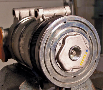
The clutch on the front of the compressor is a good clue as to the type of compressor the BMW you’re working on uses. The activation of the compressor clutch is controlled by the IHKA (Intergriertes Heizung und Klima Automatic or Integrated Automatic Heating and Cooling) module. If the evaporator temperature is above 37° F, and the refrigerant pressure sensor indicates acceptable pressure, the control module then enables the ECM to activate the compressor.
The system will deactivate the compressor if it detects any of the following conditions:
1. The ECM detects full engine load or aggressive throttle position.
2. The evaporator temperature is less than 35° F.
3. The coolant temperature is more than 245° F.
4. The refrigerant pressure sensor (located in the high side) indicates pressure is too low or too high.
If you do not have a scan tool that can monitor the clutch Parameter IDs (PIDs), you can measure the current pulled by the compressor clutch coil by clamping an amp probe on the positive wire going to the clutch. If you have an enhanced scan tool, the A/C clutch can be operated independently to observe operation.
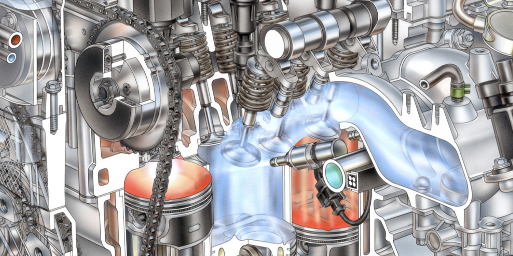
On moderns BMWs, the most common type of compressor used is the swash-plate compressor (also known as a wobbler compressor); this fits into the reciprocating-compressor category. The swash plate converts the rotary motion of the driveshaft into an axial motion.
It changes the pivot point of the pistons to change the stroke. This varying piston stroke delivers a variable cylinder displacement. The compressor and control module can change the stroke for the most efficient HVAC operation and fuel economy.
Depending on the design, this may involve five to seven pistons that are arranged in a circle around the driveshaft. An intake/pressure valve is assigned to each piston, and these valves open/close automatically in time with the operating cycle.
Depending on the application, the compressor may have a magnetic clutch. Clutchless compressors found on some BMWs are constantly engaged when the engine is running.
As mentioned earlier, the compressor output is always variable displacement and is controlled internally by either a “mechanical” control valve that operates solely on an A/C pressure differential and does not need electronic signals, or by an “electronic” control valve that is operated directly by signals from the IHKA control module, depending on the system.
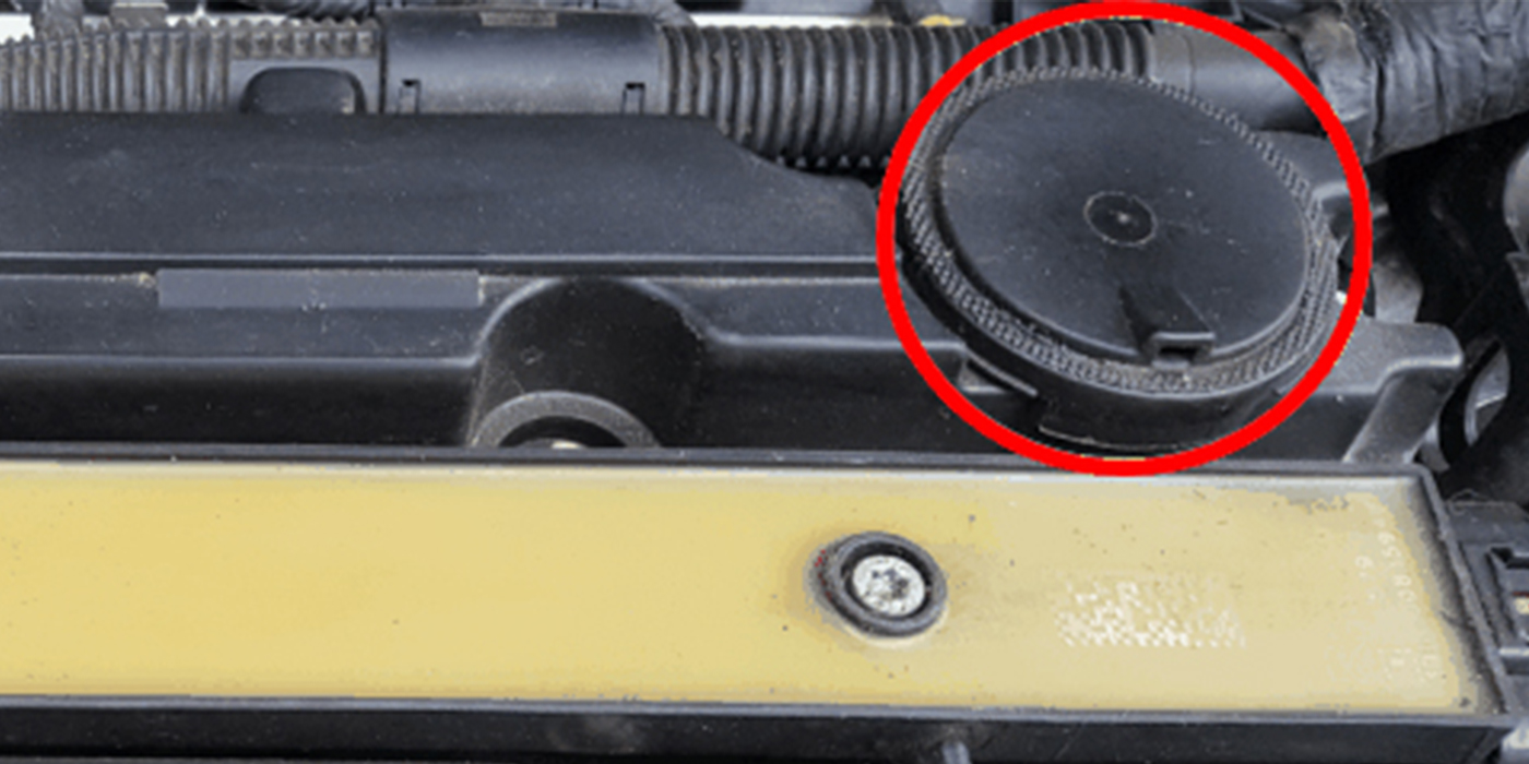
On systems with a mechanical control valve, the displacement is controlled by changes in internal pressure, which is modified by a mechanical control valve mounted in the rear of the compressor. The mechanical control valve contains a pressure-sensitive bellows exposed to suction-side pressure. The bellows acts on a ball and pin valve that is exposed to high-side pressure. The bellows also controls a bleed port that is exposed to suction-side pressure.
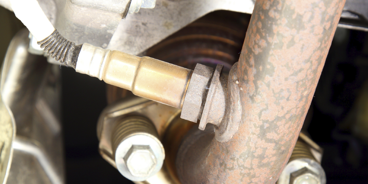
Pressure in the crankcase is increased for reduced stroke and displacement. This increases the pressure behind the pistons and reduces the angle of the wobble plate. See Photo 1. 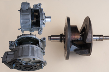
At higher engine rpm, and when the load on the system is low, the swash plate moves so that the piston travel is shortened. This reduces the constant high-load output of the compressor any time the A/C system is on. It also reduces the cycling of the compressor due to the low temperature of the evaporator (the evaporator temperature sensor causes the system to cycle at 37° F), resulting in improved fuel economy.
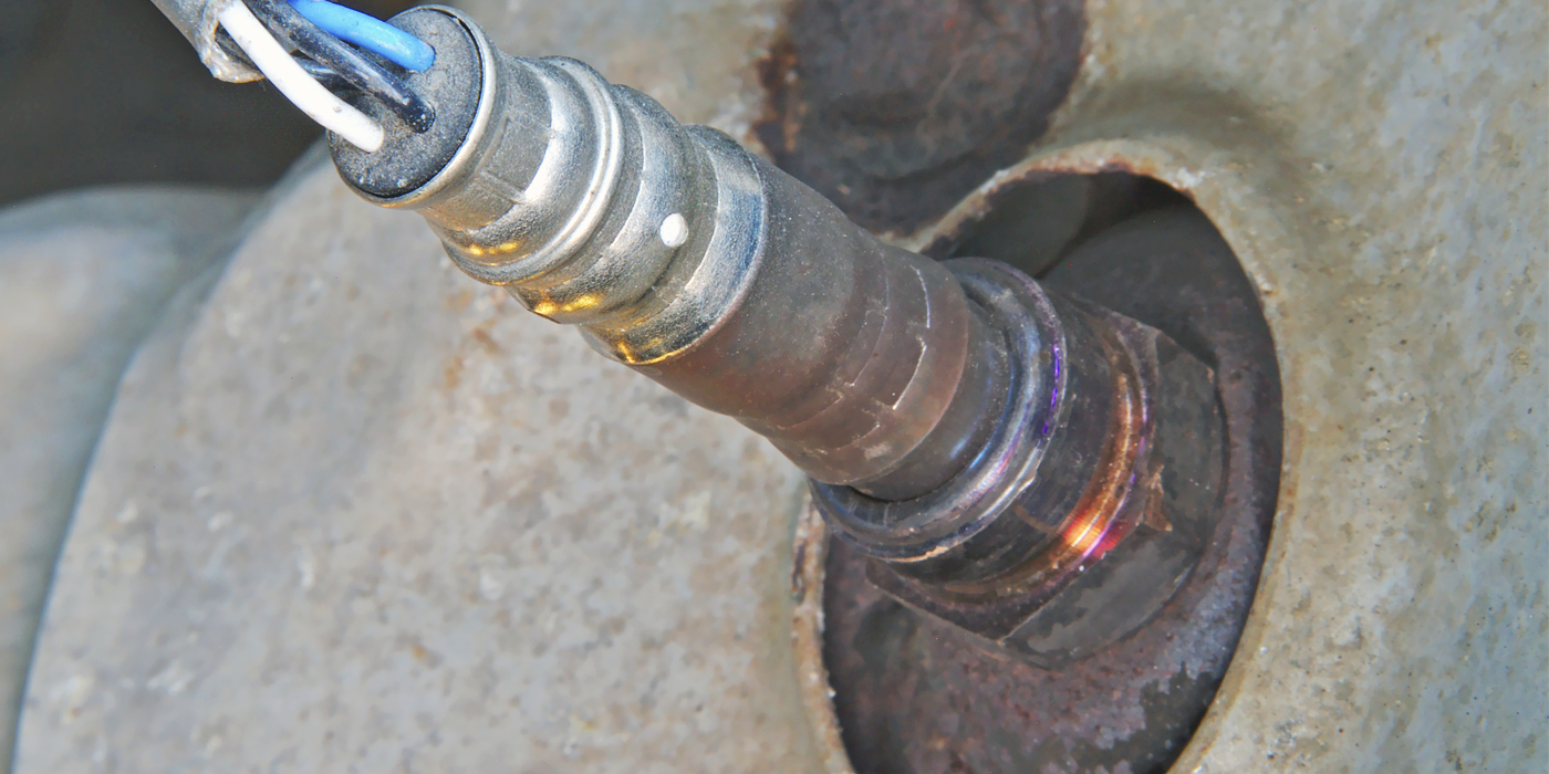
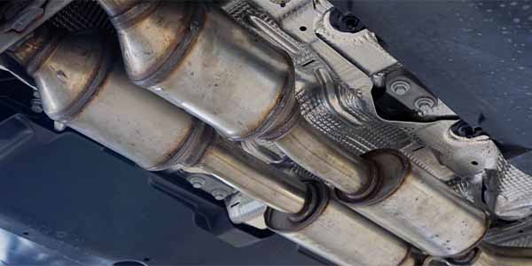
Pressure inside the crankcase is reduced for increased stroke and displacement. The opposing internal forces cause the wobble plate to tilt at a greater angle (see Photo 2). The inclination of the swash plate changes, determining the displacement volume and, therefore, the refrigerating capacity. The compressor output capacity (and therefore the delivery volume) can be set from 0-2% minimum to 100% maximum. 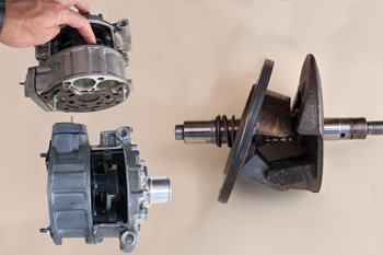
At low engine RPM and/or high-temperature loads, the travel (displacement) of the compressor pistons are at the maximum point. This allows the compressor to provide maximum cooling efficiency at idle speeds and when high output is required.
On systems with an electronic control valve, the IHKA control unit can infinitely change the displacement of the compressor, depending on the ventilation temperature, exterior and interior temperatures, as well as the target and actual evaporator’s temperature. The voltage signal to the valve is a pulse-width-modulated voltage signal.
For example, the IHKA control unit activates the control valve accordingly when a higher refrigerating capacity is required. A pulse width-modulated voltage signal moves a tappet (plunger) in the control valve. The adjustment range is determined by the amount of time the voltage is applied. The adjustment varies the opening cross-section in the control valve between the high-pressure and low-pressure sides of the crankcase.
The evaporator temperature is controlled to a value between 35° F and 46° F, depending on the cooling power request. The temperature sensor signal in the evaporator is used as a feedback signal to the IHKA control unit. The refrigerant request is limited by the potential evaporating power of the evaporator. The evaporator is prevented from icing up by controlling the compressor output.
SERVICE IMPLICATIONS
When servicing the system, techs need to keep in mind that refrigerant pressure is directly proportional to its temperature, so as the temperature goes up so does the pressure, and vice versa.
Refrigerant in the A/C system is prompted to change its state from a liquid to a gas and back again. During every change of state, heat is either absorbed or dispersed in the process. This thermodynamic property is put to use in the low and high sides of all A/C systems.
The low-side pressure is a direct reading of the evaporator temperature and its heat exchanging capabilities. Low-side pressures should average +/- 2 bar. (28 to 32 psi), meaning that actual pressure of a variable displacement compressor/TEV system can be between 1 to 3 bar. or (15 to 45 psi) at any given time.
The high-side pressure is a direct reading of the condenser cooling efficiency. Although high-side pressures may vary between 150 to 300 psi, normally they should be about 2 to 2.5 times the ambient temperature. Depending on humidity, an outside temperature of 80° F should produce pressure of 160 to 200 psi on the high side.
When the high-side pressure is way above normal, it may indicate that the condenser auxiliary cooling fan is not sufficiently cooling the refrigerant. Proper airflow across the condenser ensures the efficiency of the entire system. The cooler the refrigerant leaving the condenser, the lower its pressure; and, the lower the temperature of the refrigerant entering the evaporator, the more heat can be absorbed from the passenger compartment.
Pressure gauges are indispensable when diagnosing an A/C system, but they are incapable of measuring the quantity or, for that matter, the type of refrigerant in the system. The refrigerant capacity of an A/C system can be found on the A/C label under the hood and in the technical information relating to the specific system.
For a quick check before and after working on an A/C system, note the ambient humidity and ambient temperature, close all the windows and doors, raise the engine speed between 1,500-2,000 rpm, set the blower at medium speed, set the temp desired at Max Cold, turn the A/C button on and leave the system working for three minutes. The temperature at the center vent should be 20° F less than the ambient temperature.
Why Oil Balancing is Critical When Replacing a Compressor
 The purpose of oil balancing is to make sure the amount of oil in the A/C system remains at the correct level. The first thing to consider when performing the process is the amount of oil contained in the replacement compressor. This can vary from a full charge of oil (8 oz./236 mL), to a half charge of oil or no oil at all. If oil is contained in the replacement compressor, it will have to be removed and reinstalled in the correct amount to properly balance the system.
When performing a compressor oil balance, always follow the instructions provided with the compressor or in the vehicle service manual to know how much oil to add to the compressor prior to vehicle installation. Most times, oil balancing involves draining and measuring the oil from the failed compressor, followed by adding a specific volume of new oil to the replacement compressor.
It’s also important to use the viscosity of oil recommended by the compressor manufacturer. If the compressor requires heavier-weight oil, such as PAG 150, but PAG 46, which is lighter-weight, is used, the result could be noisy compressor operation and premature wear.
After adding the oil to the compressor, a good service tip is to rotate the compressor clutch at least four turns prior to compressor installation. Rotating the clutch circulates oil through the compressor, which reduces the potential of compressor damage due to dry bearings, and it also reduces initial torque when the clutch is first engaged.
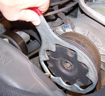
Rotating the compressor clutch is usually done by hand or with a spanner wrench. Another option is a compressor turning tool. On direct-drive compressors, the pulley and clutch are one and the same.
The turning tool performs the same function as the spanner wrench, but it’s installed on the threaded hub of the clutch. After the turning tool is installed, use a wrench to turn the tool and clutch. The turning tool can be used on some clutches that cannot accept a spanner wrench because of clutch design, or where a solid grip by the spanner wrench cannot be achieved. The turning tool can also be used in place of the spanner wrench, providing an easier method of clutch rotation, and it can be done off or on the vehicle.
Never use a socket on the shaft nut or bolt to rotate the clutch. Doing so may affect the air gap between the clutch driver and compressor pulley, resulting in compressor issues.
– Courtesy of Delphi Product & Service Solutions