A simple cable linking the gas pedal to the throttle plate just wasn’t good enough for engineers, who have now complicated the design with throttle-by-wire. Why do engineers do these things to us? That expensive throttle body can’t be cheaper than a little throttle cable — or can it? Does this design provide any advantages for the manufacturer or consumer?
Benefits of Throttle-By-Wire:
1. Traction and Stability Control: With throttle-by-wire, it is easier to shut down the power than to fight it with the brakes.
2. Better Response: When the throttle cable is pulled on an older system, the engine control module then has to fight the sudden throttle angle by adding more fuel and changing the ignition. Throttle-by-wire creates harmony between the throttle angle, ignition and fuel, which allows the engine to create more torque and power. Also, throttle-by-wire can better utilize variable valve timing.
3. Transmission Shifts: With throttle-by-wire, the engine control module and transmission can control power and shifts so that power is applied smoothly and with the least amount of shock to the system.
4. Rev Limits: Throttle-by-wire allows the engine control module to limit vehicle speed and engine rev through throttle control, rather than inducing misfires. Also, adding factory cruise control to a vehicle that wasn’t originally equipped with cruise becomes a case of just installing a switch and updating the software.
Inside Throttle-By-Wire
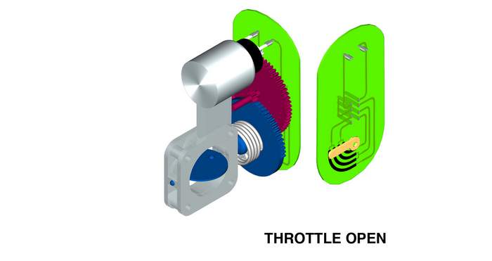
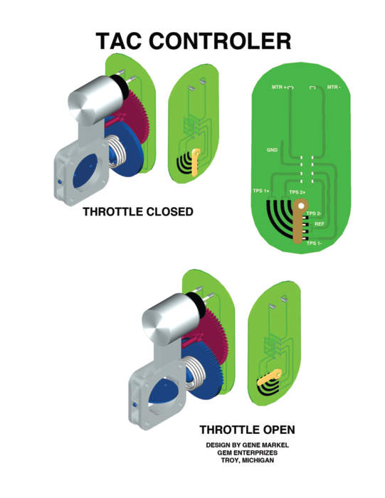
The electronic throttle body is very similar to the cable-operated throttle body, with a few notable changes. Among the most noticeable is the addition of the throttle actuator control motor (TAC). This motor is used to open and close the throttle plate based on direct commands from the engine control module.
The TAC motor turns two reduction gears inside the throttle body that link the drive gear from the motor to the throttle plate shaft.
On most systems, idle speed is controlled completely by throttle plate angle. Gone are the idle air control motors and the tiny drilled hole in the throttle plate.
The typical throttle body has two springs inside. One spring is for throttle plate return and the other is a “limp home” spring. The limp home spring is set to open the throttle enough to move the vehicle if the power to the DC motor is lost. This will result in an airflow equal to a high idle and will produce a constant speed of about 25-30 mph. On some vehicles, idle rpm will not be high because the ignition system will induce misfire to control the engine speed.
The throttle position sensor (TPS) has been redesigned for the throttle-by-wire. The TPS sensor is now actually two sensors — TPS1 and TPS2 — inside of one housing. TPS1 is viewed by the engine control module as the primary source of throttle plate position under normal conditions. TPS1 behaves in the reverse of a traditional TPS (it has a negative slope). In the at-rest position, the voltage is near the 5-volt reference voltage. As the throttle plate opens, the voltage from TPS1 lowers.
TPS2 is used to crosscheck TPS1. TPS2 is also used by the system for small throttle angle changes because it has better resolution than TPS1. In the event that TPS1 fails, TPS2 becomes the computer’s primary source of throttle plate position. The voltage from TPS2 behaves in the traditional TPS manner. In the at-rest position, the voltage is less than 1 volt and raises toward reference voltage as the throttle plate opens.
TPS1 and TPS2 do not mimic each other in voltage value. As you can see, the slope angle of TPS2 is about twice that of TPS1. TPS1 provides a signal that covers the entire sweep, which is similar to the behavior of older versions of TPS on cable-operated systems. The only real difference is the negative slope of TPS1. TPS2, however, reaches its peak voltage twice as fast. The voltage slopes change at different rates to further isolate TPS1 from TPS2 in the eyes of the engine control module.