 Doing mobile diagnostics, I obviously get more than my share of no-code drivability problems. Case in point, I was asked by a client shop to “take a quick look” at a stalling complaint on a 2003 Ford Explorer with a cable-operated throttle.
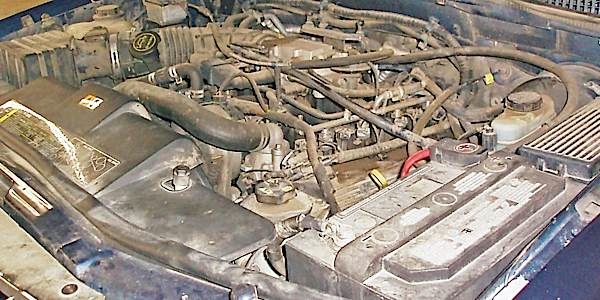
Sometimes we get lucky, so I took the shop’s scan tool and discovered that the stalling complaint was a no-code condition that occurred only after a 15-minute warm-up. The idle speed then began floating up and down until the engine suddenly stalled. With the transmission engaged, I had to power-brake the idle speed to keep the engine running (see Photo 1).
Data Collection
Going from a quick look to an intensive study, the scan tool’s list of parameter indicators (PIDs) indicated that the Idle Air Control (IAC) was hanging around a normal 48% positive duty cycle. As the idle speed dropped after warm-up, I could hear the familiar sucking sound of the IAC opening to increase idle speed. The scan tool also indicated “no fault” in the IAC Fault PID.
After a few gasping surges, the engine would suddenly stall, as if the ignition was turned off. Adding propane to richen the fuel mixture didn’t help with the stall and neither did removing a vacuum hose to lean out the mixture. But holding the throttle at 1,500 rpm would keep the engine running, which is indicative of a bad IAC valve. Cleaning the throttle assembly made no difference in performance.
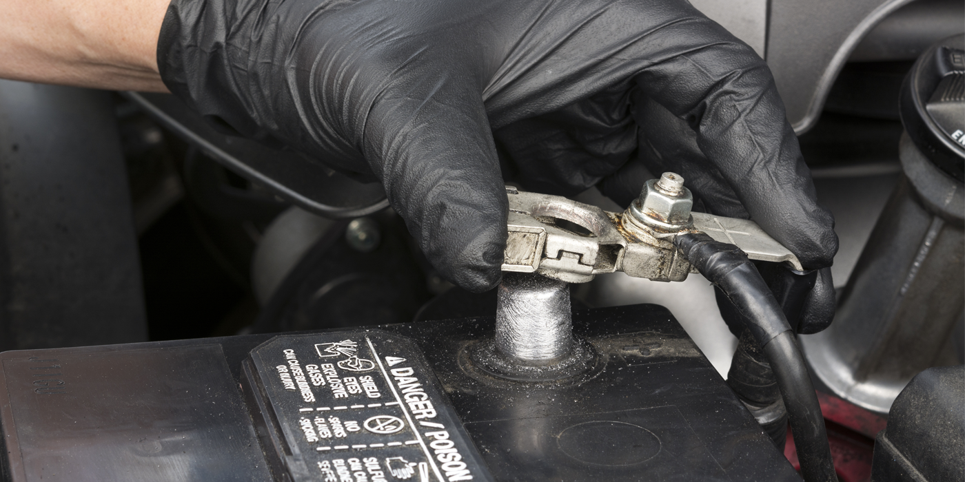
I checked the diagnostic memory for a P1000 DTC, which would indicate if the no-code condition had been caused by disconnecting the battery cables. There wasn’t any P1000 DTC, so I polled all modules, looking for codes indicating low battery voltage and all systems were clear on that point. Always keep in mind that low battery voltage can erase codes during cranking. The fact is, the scan tool was using indicated that I had a pure, no-code stalling condition, which was remarkable because the stalling condition was a hard failure that could easily be duplicated.
The Laundry List
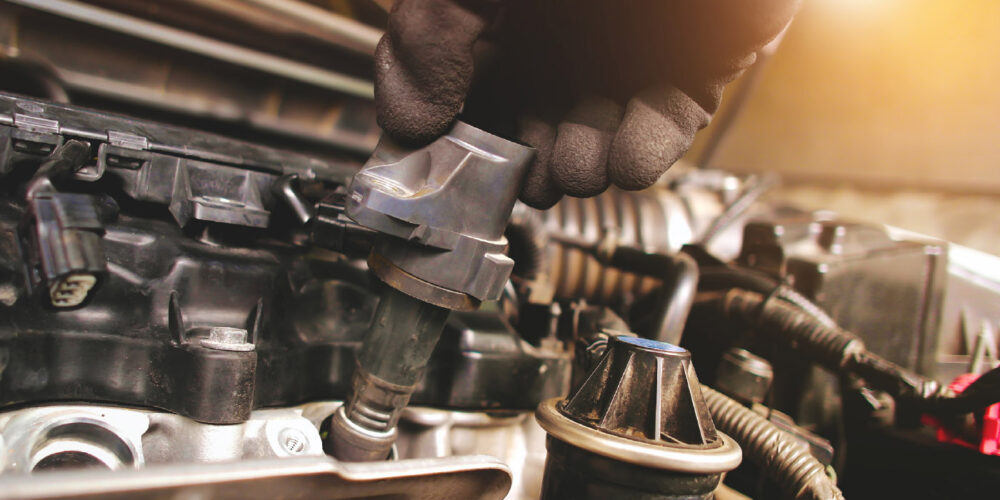
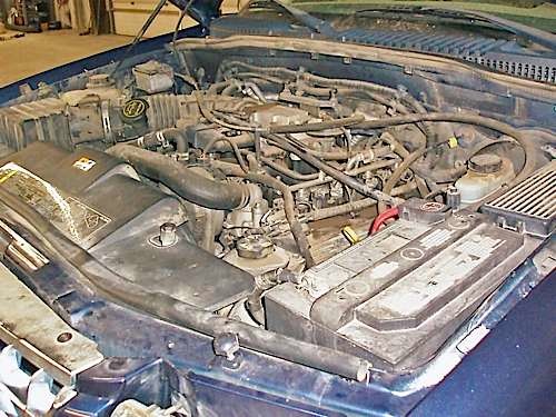
The difficulties of diagnosing no-code drivability problems are best summed up by one of Yogi Berra’s famous quotes, “When you come to a fork in the road, take it.” According to my tech hotline’s data base, defective IAC valves topped their list of probable causes of stalling 2003 Ford Explorers. But the fork in the road occurred when I heard the Explorer’s idle air control (IAC) solenoid valve open up as the engine lost speed and I’m seeing the IAC PID ranging between an ideal 40% to 48% at hot idle speed. So, I’m assuming I have idle speed control and, intuitively, I’m thinking a crankshaft position (CKP) sensor issue (see Photo 2).

While the update speed for scan tools is too slow to accurately capture split-second events, several “movies” of the stalling event seemed to indicate that PCM was failing to trigger the fuel injectors. But, while the CKP is a vital input for fuel control, we don’t want to forget the camshaft (CMP), mass air flow (MAF), and throttle position (TP) sensors can cause fuel control failures as well.
What the PCM Sees
At this point, we’re into pure speculation. But let’s see what the enabling criteria might be for two “global” codes applicable to the Explorer’s 4.6-liter engine, P0320 (CKP) and P0506 (IAC). The enable criteria for P0320 is two pulses missing in succession from the CKP data. This appears to be a black-and-white set point, so why would we lose the CKP signal without the PCM seeing it? In some cases, a CKP sensor failure code can be a two-trip code, which means that the initial failure is stored in pending rather than current codes. Such was not the case here.
The Explorer’s CKP sensor is a two-wire, variable reluctance sensor that can behave erratically if excessive clearance develops between the sensor and the crankshaft reluctor. The two-wire CKP can also behave erratically if the sensor itself is weak. Just a guess, but the Ford’s sine-wave voltage signal could be weak enough to prevent the PCM from counting enough CKP pulses to set the P0320 DTC.
Before we connect our lab scope, remember that two-wire variable reluctance sensors are also speed-sensitive. Most two-wire CKP reluctance sensors need at least 150 cranking rpm to generate a readable signal. I might be looking at a scenario in which signal strength might be affected by either low crankshaft speed or by a weak CKP sensor or both.
In any case, the CKP sensor is a primary input needed to keep the engine management system operating and, without a known-good CKP waveform for comparison, my diagnosis is probably going nowhere. So, at this point I’m going to take the first fork in the road by replacing the CKP sensor, which is easier and perhaps cheaper, spending valuable diagnostic time trying to catch a signal glitch with a lab scope (see Photo 3).
How the IAC Works
As for a hypothetical P0506 (low idle speed) code, the PCM is looking for a mismatch between commanded and indicated idle speed. Remember that the scan tool is displaying the IAC duty cycle and I’m hearing the IAC respond to the PCM’s commands. So, the PCM might not be seeing enough difference between commanded and indicated idle speed to set a P0506 DTC.
The Ford idle air control (IAC) solenoid valve consists of a spring-loaded idle air valve, a B+ voltage source shared with the fuel injectors, and a B- ground circuit terminating at the PCM’s IAC driver. Key-on, engine cranking, the IAC remains open. Once the engine starts, the duty cycle or “on-time” of each pulse varies according to commanded idle speed.
Practically all throttle bores accumulate carbon and varnish from PCV and EGR flow into the intake manifold. To reduce throttle bore deposits, many Ford throttle bore assemblies of this vintage are coated with Teflon. Cable-operated throttle plates, such as the one on this Ford, use a stop-screw adjustment to prevent the throttle plate from contacting the throttle bore surface at closed throttle. The stop-screw also prevents the throttle plate from damaging the protective coating and the throttle plate from sticking in the throttle bore.
This stop-screw also maintains a small base air flow around the throttle plate. With a clean throttle bore and under ideal conditions, many Fords operate at around a 48% duty cycle. A normal duty cycle range is a handy number to remember because normal duty cycle is reduced if a vacuum leak develops. Similarly, if the throttle bore accumulates varnish, normal duty cycle increases to make up for the lack of base air flow. It’s also important to know that the Ford IAC is very reliable. As a percentage of idle speed complaints, I’ve encountered very few defective Ford IAC valves during the past twenty years.
Scan Tool Uses
A major problem with this diagnosis was the lack of good scan tool data. I would have saved a lot of time if the scan tool had displayed a CKP and CMP synchronization PID so I could evaluate CKP/CMP activity. The same with a commanded (desired) and indicated (actual) idle speed PID. That said, it’s possible that Ford never engineered a complete data stream into the PCM’s software. It’s equally possible that the aftermarket scan tool manufacturer edited the Ford data stream to fit the scan tool’s data processing capabilities. The only way to evaluate this lack of data would be to compare the aftermarket scan tool data with the original equipment manufacturer (OEM) scan tool data.
The Smoking Gun
With the CKP sensor replaced, I connected my scan tool to observe the actual IAC duty cycle. Next, I set my digital multimeter (DMM) to the duty cycle mode and connected it to the IAC ground circuit so I could get a numerical measurement of duty cycle. If your DMM doesn’t measure duty cycle, the dc voltage scale should normally indicate about 9.0 volts (equal to about 40%-50% duty cycle) at hot idle.
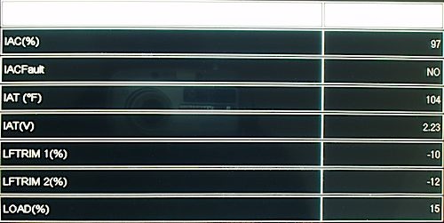
That said, we spent nearly an hour working over a hot engine before we found our “smoking gun.” While the DMM reading didn’t perfectly correlate with the indicated reading on the scan tool, the IAC duty cycle remained relatively stable until the engine suddenly began gasping for air. My DMM is now reading “OL,” which is indicating “overload” or 100% duty cycle. The scan tool is indicating 97% duty cycle. Notice in Photo No. 5 that the scan tool is also showing “No IAC Fault,” which indicates a no-code condition.
Obviously, the PCM was trying to pull the IAC open, but was failing. I then tapped the IAC solenoid valve with a small hammer and, just as suddenly, the idle speed and duty cycle returned to normal. We had indeed found a smoking gun that proved beyond a doubt that the IAC wasn’t tracking with the PCM (see Photo 4).
The Fork in the Road
According to my hot line’s “fix” data, the IAC was the leading cause of stalling complaints on the 2003 Ford Explorers with cable-operated throttles. Using what we call a “statistical” diagnosis, I might have fixed the stalling complaint based upon this probability alone. But it didn’t explain the sudden stalling symptom, which led to the all-too familiar diagnostic fork in the road. At this point, I thought it was better to replace a suspect part with new and get on with the diagnosis.
In hindsight, although I could hear the familiar sucking sound of the IAC opening up, the IAC itself evidently wasn’t tracking with the PCM’s commands. In this diagnostic scenario, the pulse-modulated IAC valve itself would momentarily stick closed and wouldn’t open, even at 100% positive duty cycle. It’s also possible that the IAC had an internal electrical open or short that was sensitive to high operating temperatures that would allow the IAC to momentarily stick closed. In this case, replacing one part so I could diagnose another proved to be the fork in the road that led to solving this month’s Diagnostic Dilemma.
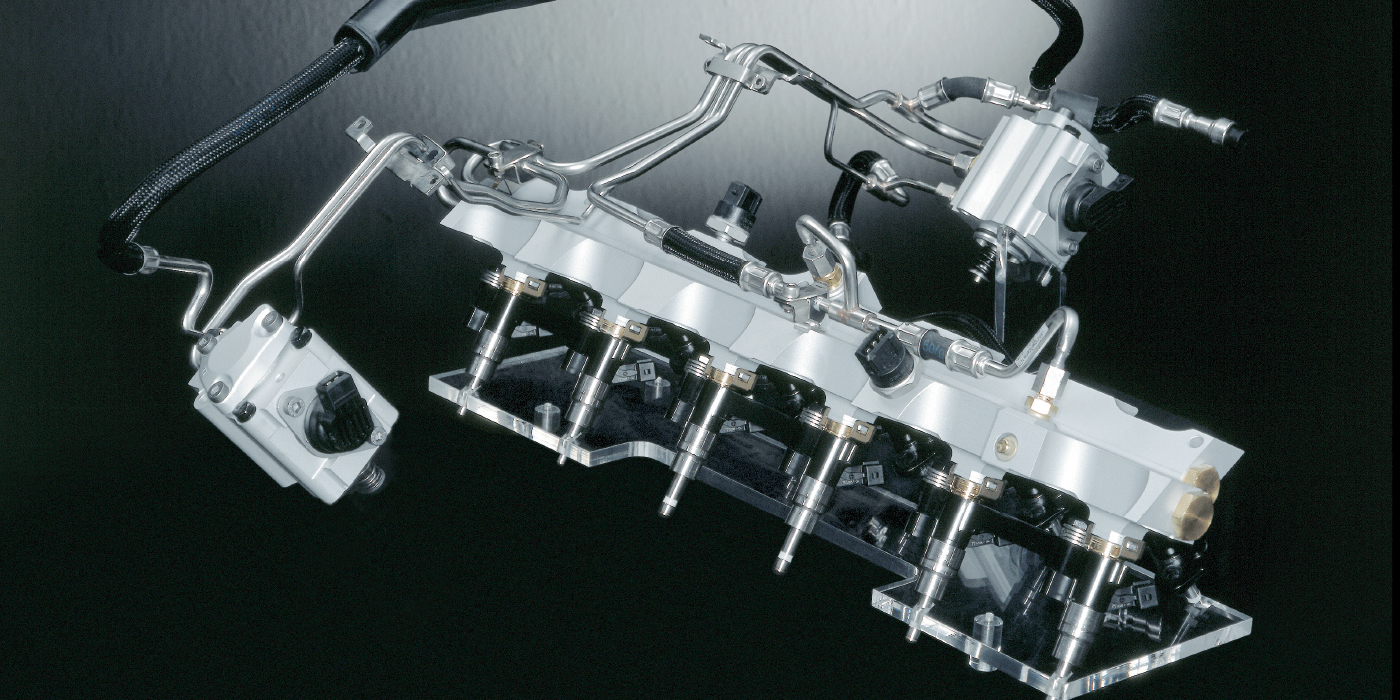
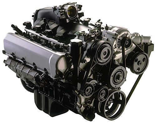
Photo 1 The IAC valve on this 4.6-liter Ford is attached directly to the front of the throttle body.
Photo 2 During warm-up, the duty cycle on the B- lead to the PCM will read high. At 9.0 volts, the meter is reading about 33% on-time, 67% off-time with a hot engine.
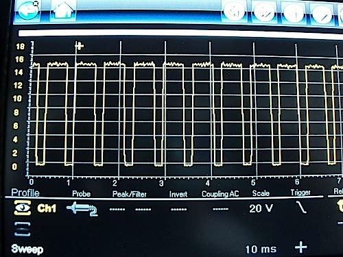
Photo 3 This square-wave form doesn’t indicate any electrical problems within the IAC circuit or the PCM driver, at least at this time.
Photo 4 The smoking gun in this case was the discrepancy between IAC% and the IAC Fault PIDS.
The IAC is a simple spring-loaded valve that opens when the PCM pulls the IAC solenoid circuit to ground.