
This month’s Diagnostic Dilemma turns the page back to September 10, 2015 when I got a phone call from a local undercar shop inquiring if I had the tools to check the ECM connector pin fit on a 2012 Chevrolet Impala with the flex-fuel, 3.6L gasoline direct fuel injection engine. In response to an intermittent loss of power complaint, the shop had found a technical service bulletin (TSB) indicating that loose PCM connections can cause a loss of fuel pressure on the GDI engine’s high-pressure fuel rail and set codes P00C6 and P228C. While I haven’t invested in a master testing kit, I do maintain an inventory of drill sizes and flat connectors that will test fit and tension on most ECM applications. With scope, scan tool, and pin testers in hand, I ventured downtown to one of our local undercar shops to test the pin fit of the Chevy Impala’s ECM.
Like many diagnostic technicians, I spend a large part of my spare time reading what I can on the International Automotive Technicians Network (iATN), looking through mechanical engineering and lubrication journals, and scanning articles in trade magazines, just as you’re doing right now. I’ve also made the rounds of GDI training classes presented by parts suppliers and manufacturers of GDI components, as well. Not to take anything away from training, but the leap from the classroom into the real world of GDI diagnostics is like leaping from a hot sauna into a pool of ice water.

We know, for example, that GDI has a major problem with carbon accumulating on the intake valves, which causes leaking intake valves and, in turn, cylinder misfires. If we read an oil engineering journal, it might describe problems with oil-borne hard carbon particles aggravating timing chain wear. Mechanical engineering journals describe how engineers juggle high compression ratios with turbocharging and variable valve timing to achieve optimum cylinder pressures. Whatever the case, as the new GDI vehicles now come out of warranty, we’re often going to find ourselves struggling to keep up with what I call the “nuances” of GDI diagnosis and repair.
SYSTEM OVERVIEW
Before we take our plunge into the technical ice water, let’s highlight the features of the 2012 Impala’s GDI system as they apply to our diagnosis. First, the engine features a high 11.5:1 compression ratio, which is typical of GDI engines. A returnless pulse-modulated, turbine-style fuel pump located in the fuel tank supplies 45-75 psi to the high-pressure fuel pump. To prevent over-pressurization, a mechanical fuel pressure relief valve is built into the electric pump. Through data feedback provided by an in-line fuel pressure sensor, the engine control module (ECM) commands the desired fuel pressure to the fuel pump control module via GMLAN serial data messaging. A flex-fuel sensor is also located in the fuel line to relay ethanol content to the ECM so it can make the necessary air/fuel ratio corrections for ethanol content. Due to how ethanol fuels are refined, the sensor will indicate slightly less ethanol content than advertised on the gas pump. In my testing, the flex-fuel sensor indicated about 7% ethanol content compared to approximately 10% measured ethanol content.
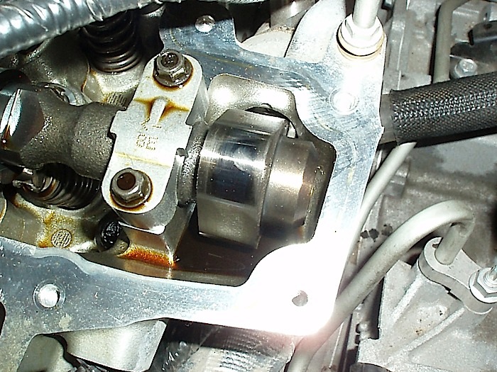
The high-pressure fuel pump is driven by a three-lobe cam located at the end of the bank 2 exhaust camshaft. Fuel pump output pressure is controlled by a solenoid-operated pressure control valve built into the fuel pump assembly. If the solenoid is disconnected, the fuel pump produces maximum pressure. The GDI system injects fuel directly into the cylinder. The ECM opens the injectors via 65 volts produced by a boost capacitor in the ECM. The 65-volt boost phase initially opens the injector, and the injector is held open afterward with battery voltage. A high-pressure sensor is incorporated into the fuel rail, which provides data feedback to the ECM. Depending upon the brand of scan tool, high fuel pressure values will be expressed in megapascals (MPa) or in pounds per square inch (psi). One MPa equals approximately 145 psi.
CODES, CODES, CODES
I knew that I might be in trouble when I pulled the 14 individual modules on the ‘12 Impala and discovered that 12 of them contained two or more trouble codes. In theory, I should have recorded all codes. Many “ghost” codes are usually caused by technician disconnects or low voltage from the ignition switch or relay box and aren’t likely to repeat. And we’re looking at a car just out of the original 36-month warranty period, so how many things could actually go wrong at the same time? I cleared all codes and started the engine to see what happened next.
Initially, the engine ran fine, but with an illuminated “check engine” light, it went into “reduced power” mode. This meant, of course, that the electronic throttle had defaulted to a minimum function mode. After the engine warmed up, a strong rotten-egg smell began emanating from the exhaust, indicating that the engine was being over-fueled. When the engine began to chug, I floor-boarded the throttle to initiate a “clear-flood” mode.
Suddenly, the engine cleared and began running normally. After a thorough warm-up, we test-drove the Impala and it ran great for at least 10 miles. The history codes revealed a P00C6 (low fuel pressure, cold), P0151 and P0157 (low voltage), B2S1 and B2S2 oxygen sensors, P0300 (general engine misfire), P228C (fuel pressure regulator solenoid performance) and CO 242 and CO 561 (ABS communications).
ANALYZING THE CODES
The P00C6 code indicates low fuel pressure during warm-up. Jumping ahead, the P228C indicates a problem with the high-pressure fuel pump solenoid performance. The P228C also initiates the reduced-power electronic throttle mode. The P0151 and P0157 codes indicate a zero-voltage condition at the bank 2 upstream and downstream oxygen sensors. The CO242 and CO561 ABS codes repeated after being cleared and remained a concern. As for code definitions, the P228C is described in some databases as low fuel pressure at operating temperature.
ANALYZING THE DATA LINES
The ‘12 Impala 3.6L engine produces many windows of data — so many that, at times, it’s very confusing. And, depending upon your individual scan tool, the high fuel-pressure data is sometimes expressed as psi, MPa, or both. There also were data lines that I absolutely missed. When reviewing for this article, for example, I found a data line labeled “reduced engine power history” followed by the warning, “fuel system malfunction,” which would have simplified the initial diagnosis.
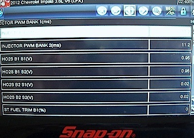
As for fuel trims, keep in mind that the engine was operating in “limp” mode, which means that the ECM is operating in open-loop on a fixed injector pulse. Consequently, the short-term fuel trims disappeared, leaving only the long-term trim data for analysis. Going back to the P0151 and P0157 codes, both were confirmed by the long-term fuel trims, which were approximately minus 10 on bank 1 and plus 25 on bank 2. Once I became accustomed to the windows of data, I found the engine running normally would produce in the 500 psi range at idle and at 2,175 psi under wide-open throttle (WOT). When it ran poorly, the fuel rail would hover in the 100 psi to 200 psi range.
OPERATING STRATEGIES
I’m sure you’re wondering how an engine running low on fuel pressure could over-fuel itself, and why bank 1 could over-fuel while bank 2 was starved for fuel. I’ll attempt to explain what I determined to be operating strategies: The engine would idle at 2 milliseconds (ms) injector pulse under normal operation. But, once code P00C6 was set, the ECM commanded the fuel injectors to 11 ms at idle. I’m suspecting that the over-fueling is an operating strategy used when the fuel rail pressure falls below desired levels.
As for bank 1 over-fueling while bank 2 was under-fueling, I simply didn’t have enough time to follow up in a production shop environment. Since problems with bank 2 exhaust camshaft will affect operation of the high-pressure pump, I thought I had a camshaft phaser or solenoid malfunction. But with no valve timing codes, that wasn’t the case. Oddly enough, we discovered that spark plugs from both banks were heavily sooted from over-fueling. Since the electronic throttle control went into “reduced power” mode, the traction control light illuminated. The last operating strategy that I observed was the ECM actually shutting off the engine and disabling the starter when the engine began running poorly. A one-minute wait restored both the starter and engine functions.
DANGER, WILL ROBINSON
I don’t know if you remember the old 1960s TV series, “Lost in Space,” about a family named Robinson lost on a distant planet. Will Robinson, the young boy played by actor Billy Mumy, was followed around the dangerous planet by a robot that attended to his safety and welfare. After reflecting on the complexities of this particular case study, the first words that came to my mind were the robot’s familiar warning: “Danger, Will Robinson, Danger!” With that admonition in mind, I began wondering if we hadn’t inherited a “warranty baby” just out of its original manufacturer’s warranty period that had been peddled to a new owner.
The first “Danger” item we discovered was a missing Schrader valve cap on the fuel supply pump. The next “Danger” item was a broken release tab on the solenoid connector, which was ample proof that another person had been trying to solve this very same problem. (Danger, Will Robinson!)
After questioning the owner, we also discovered that the Impala had been bought from a used-car auction in Texas. (Danger, Will Robinson!)
Since further research was in order, my client’s shop called our local GM dealership to check on the service history of the vehicle. Other than several recalls, including a protective shield installed on the transmission, no other warranty problems were reported.
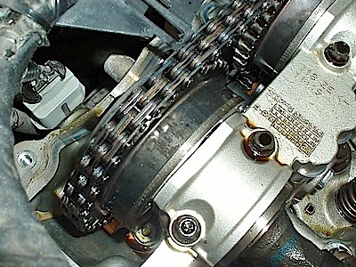
Thus assured, we began a physical examination of the engine. Removal of the camshaft cover as a precautionary measure indicated that the oil had been regularly changed and the high-pressure fuel pump cam was in perfect condition, as were the bank 2 exhaust valve train and timing chains. But, the fact that the engine could run very poorly and then suddenly run perfectly indicated an electrical problem. And, the fuel bypass solenoid is the only electrical part of the mechanical high-pressure fuel pump.
SYMPTOM VERSUS FAILURE
Since 2008, many engines have been programmed to deal with various common failures by defaulting into an emergency operating strategy. Let’s remember, for example, that this is an 11.5:1 compression ratio engine. This engine could conceivably go into severe detonation if the air/fuel mixture leans out when the fuel rail pressure becomes too low. Strictly as speculation, enriching the air/fuel ratio would prevent detonation by cooling the pistons and combustion chambers with gasoline. When diagnosing modern vehicles, avoid symptom diagnosis. In many cases, you’ll find yourself trying to diagnose an “operating strategy” rather than a “symptom.”
PAINTING BY THE NUMBERS
The solution to this month’s Diagnostic Dilemma was “painting by the numbers,” which is why I always recommend printing out the data sheet for any primary trouble codes. The diagnostic information for P00C6 is, for example, five pages long and includes a diagnostic chart for the high-pressure fuel pump. I won’t attempt to summarize the diagnostics in this space, other than to say that I’d already determined that a high-pressure fuel pump replacement was needed. The P00C6 diagnostics merely confirmed my diagnosis. In closing, I’d like to mention that the physical layout of this GDI system wasn’t conducive to using a lab scope, pressure transducer or even a pressure wave sensor. Not that these methods couldn’t be used, but none would have affected the outcome of this month’s Diagnostic Dilemma.